Common Mode Choke Analysis
Found 5 free book(s)
The G5RV Antenna System -- An Analysis
www.bvarc.org•Consensis is to use a choke at the owl / coax transition point to avoid common mode currents –Types suggested •Air Wound •Badger (W6TC) Coaxial Choke (HR 2/1980) •K9YC stacked core chokes / ref NCJ •W2DU – Maxwell “bead” choke •Note: Coiled coax chokes (10 turns on a #10) will not have the frequency range needed 80M thru

How does it Work? Common Mode Chokes - Pulse Electronics
www.pulseelectronics.comthe common mode signal that enters or leaves a PCB. X and Y capacitors are commonly used to shunt the common mode noise away from the circuits of interest, while a common mode choke is used to attenuate or dampen the noise. When placing an inductive component such as a choke in the path of current, there are a few key items one must consider.
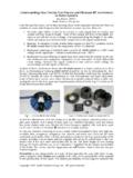
Understanding How Ferrites Can Prevent and Eliminate RF ...
audiosystemsgroup.commode voltage (between the signal conductors) and common mode voltage (an equal voltage on both signal conductors). Analysis of these mechanisms shows that RF shield current is a major contributor to all of them, so eliminating or reducing shield current should be the key to eliminating the inter-ference.
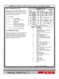
Wiring Code Identification Information
www.rambodybuilder.comcommon sense. It is to be used as a supplement to existing good design practices and standards. Additional information is in the Referenced Publications section. Performing a Failure Mode and Effects Analysis (FMEA) on each completed wiring design is a good practice to confirm the integrity of the design. This document will be revised
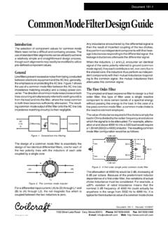
Common Mode Filter Design Guide - Coilcraft, Inc.
www.coilcraft.comFigure 4. Analysis of a second order (two pole) common mode low pass filter The design of a second order filter requires more care and analysis than a first order filter to obtain a suitable response near the cutoff point, but there is less concern needed at higher frequencies as previously mentioned.