Drawings 2
Found 5 free book(s)
2. Design of Welded Connections 2.1 Stresses
app.aws.org2.2 Drawings 2.2.1 Drawing Information. Full and complete information regarding location, type, size, and extent of all welds shall be clearly shown on the drawings. The drawings shall clearly distinguish between shop and field welds. 2.2.2 Joint Welding Sequence. Drawings of those joints, or groups of joints in which it is especially

Porch Construction Drawings
webcms.pima.gov2. Metal weep screed shall be installed a min. 4” above the earth and a min of 2” above paved surfaces 3. Finish grade shall slope away from footing and be a min 6” from sill plate 4. All concrete shall be minimum 2500 psi 5. All wood to be Douglas Fir #2 or better 6. Framing based on a 30 lbs load 7. Minimum ceiling height 7 ft, 6ft ...

Chapter 8 Multiview Drawings - McGraw Hill
www.mhhe.comCHAPTER 8 Multiview Drawings 381 8.2.2 Horizontal Plane of Projection The top viewof an object shows the width and depth di-mensions. (Figure 8.9) The top view is projected onto the horizontal plane of projection, which is a plane sus-pended above and parallel to the top of the object. 8.2.3 Profile Plane of Projection
EXPLORING PERSPECTIVE HAND DRAWING
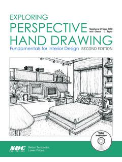
static.sdcpublications.comChapter 2 - The Box 25 . The following drawings of the box shown in the photograph represent the different views and aspects of the box design. A . two-point perspective view. also depicts a three-dimensional aspect of the box. In this view, there is a leading edge and each side appears to get smaller as they move away from the leading edge.

COMMONWEALTH OF PENNSYLVANIA
www.dot.state.pa.us2 4 " 1 2 " standard s e e n o t e 1 2 (t y p i c a l a l l 9. provide specified clearance in accordance with p o l e s) 1 2 " m i n. 12" 1 8 " 1" x 1" signal heads. 7’ minimum, 10’ maximum for pedestrian 15’ maximum for traffic signal heads; that clearance is in the range of: 8’ minimum, roadway. provide specified dimension "k" such ...