Hall Effect Current
Found 9 free book(s)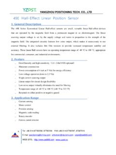
49E Hall-Effect Linear Position Sensor
p.globalsources.com49E Hall-Effect Linear Position Sensor. 1. General Description. The 49E Series Economical Linear Hall-effect sensors are small, versatile linear Hall-effect devices that are operated by the magnetic field from a permanent magnet or an electromagnet. ... Single current sourcing output Linear output for circuit design flexibility

A3144 Hall Effect Sensor - Components101
components101.comOct 31, 2005 · hall-effect switches for high-temp. operation www.allegromicro.com supply current 10 15 20 25 supply voltage in volts 0 dwg. gh-041-1 5 supply current in ma 0 2.0 4.0 6.0 8.0 10 b ≥ b op b ≤ b rp t = +25a °c 0 25 50 75 100 ambient temperature in °c-50 dwg. gh-039-1-25 125 v = 8 vcc supply current in ma 7.0 6.0 5.0 4.0 150 b ≤ b rp b ≥ ...
AN885, Brushless DC (BLDC) Motor Fundamentals
ww1.microchip.comNote: Hall Effect Theory: If an electric current carrying conductor is kept in a magnetic field, the magnetic field exerts a trans-verse force on the moving charge carriers which tends to push them to one side of the conductor. This is most evident in a thin flat conductor. A buildup of charge at

Hall Effect Experiment Manual
d2n0lz049icia2.cloudfront.netThe Hall Effect is the production of a voltage difference (the Hall voltage) across an electrical conductor, transverse to an electric current in the conductor and a magnetic field perpendicular to the current. It was discovered by Edwin Hall (1855-1938) in 1879. The Hall effect was discovered in 1879 by Edwin Herbert Hall while he was
Hall Effect Sensing and Application
sensing.honeywell.comTheory of the Hall Effect When a current-carrying conductor is placed into a magnetic field, a voltage will be generated perpendicular to both the current and the field. This principle is known as the Hall effect. Figure 2-1 illustrates the basic principle of the Hall effect. It …
Hall Effect Measurement: Hall Bar and Van der Pauw Geometry
xiaoshanxu.unl.eduMay 20, 2016 · Hall Effect Measurements Hall effect measurements commonly use two sample geometries: Long, narrow Hall bar geometries and Nearly square or circular van der Pauw geometries. Each has advantages and disadvantages. In both types of samples, a Hall voltage is developed perpendicular to a current and an applied magnetic flux.
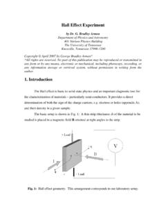
Hall Effect Experiment - University of Tennessee
www.phys.utk.edumaterial in which a current I is flowing, as shown in Fig. 3. Fig. 3: Hall effect geometry again; the strip has a thickness δ, length l, and height h. Here, the applied field B is directed only in the z direction (into the paper). The x-component of E drives the steady current I in the x direction, and a y-component of E
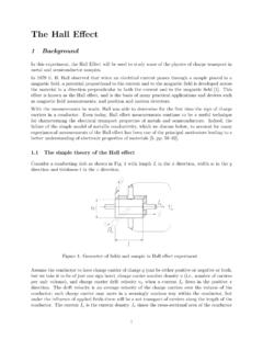
Hall Effect - University of Washington
courses.washington.eduThe Hall Effect 1 Background In this experiment, the Hall Effect will be used to study some of the physics of charge transport in metal and semiconductor samples. In 1879 E. H. Hall observed that when an electrical current passes through a sample placed in a

Hall Effect Devices - Lintronics Tech
lintronicstech.comHall Effect Review Edwin Herbert Hall discovered the Hall effect in 1879 while working on his doctoral thesis in physics. In 1880, full details of his experimentation were published in The American Journal of Science and in The Philosophical Magazine. According to the Hall effect, a particle with charge Q at velocity V, moving