Mode Converter
Found 11 free book(s)
Switch - ON Semiconductor
www.onsemi.comThe forward−mode converter can be recognized by the presence of an L −C filter on its output. The LC filter creates a DC output voltage, which is essentially the volt −time average of the LC filter’s input AC rectangular waveform. This can be expressed as: Vout Vin duty cycle (eq. 1)

Design of a Boost Converter - CORE
core.ac.ukIn a boost converter, the output voltage is greater than the input voltage – hence the name “boost”. A boost converter using a power MOSFET is shown below. Fig. 3.1.1 Circuit diagram of Boost Converter. [1] The function of boost converter can be divided into two modes, Mode 1 and Mode 2. Mode 1 begins when transistor M 1
AN149 Modeling and Loop Compensation Design of …
www.analog.comSmAll SIgnAl modelIng of PWm ConVerter PoWer StAge A switching mode power supply (SMPS), such as the buck step-down converter in Figure 4, usually has two operating modes, depending on the on/off state of its main control switch. Therefore, the supply is a time-variant, nonlinear system. To analyze and design the compensation with

The Flyback Converter - University of Colorado Boulder
ecee.colorado.eduThe flyback converter is based on the buck-boost converter. Its derivation is illustrated in Fig. 1. Figure 1(a) depicts the basic buck-boost converter, with the switch realized using a ... continuous conduction mode. 4 Solution for the conversion ratio then leads to M(D)=V V g = n D

ON Semiconductor Is Now
www.onsemi.comoperating mode #2, the output voltage is the voltage on magnetizing inductor, which is the resonant voltage of the magnetizing inductance and could be way higher than input voltage. This is the basic DC characteristics of LLC resonant converter. In regular operating mode of LLC resonant converter, 0<=Rload<∞, both operating modes happen in one

Loop Stability Analysis of Voltage Mode Buck Regulator ...
www.ti.comThe buck dc/dc converter is probably the single most common voltage converter in use. Many design resources are available: application reports, text books, and many data sheets contain comprehensive design procedures for the continuous-conduction mode of operation. For discontinuous mode, however, the same solutions do not exist in a

Topologies for switch mode power supplies
www.st.comcorrected with a current mode PWM control circuit. I Dpeak or I Cpeak ≥ V out = III - 2.2 Half bridge converter This topology can be used for an output power capability up to 500W. As for the push-pull converter, T 1 and T 2 switches are alternately turned on during a time t on. The capacitors in series across the supply fix

Switch Mode Power Supply (SMPS) Topologies
ww1.microchip.comSep 10, 2007 · CURRENT MODE CONTROL While designing a buck converter, there is always a trade-off between the inductor and the capacitor size selection. A larger inductor value means numerous turns to the magnetic core, but less ripple current (<10% of full …

Understanding Buck Power Stages Mode Power Supplies
www.ti.comcurrent mode operation, one of the two operating modes to be discussed in the next section). This report describes the steady state operation of the buck power stage in continuous-mode and discontinuous-mode operation with ideal waveforms given. The duty-cycle-to-output-voltage transfer function is given after an introduction of the PWM switch ...
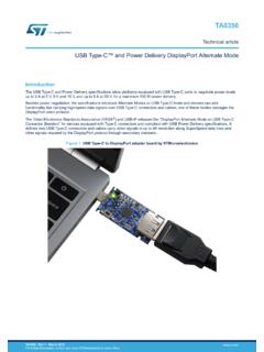
USB Type-C and Power Delivery DisplayPort Alternate Mode
www.st.com2 DisplayPort Alternate Mode roles and negotiation The VESA DisplayPort Alternate Mode and USB Type-C Connector Standard specifications describe the interactions between a video data source and a video data sink for entering or exiting Alternate Mode, as well as the commands and rules to guarantee communication consistency between the two entities.

PowerFlex 1203-USB Converter
literature.rockwellautomation.comPowerFlex 1203-USB Converter User Manual Reproduction of the contents of this manual, in whole or in part, without Important User Information Solid state equipment has operational characteristics differing from those of electromechanical equipment.