Rc Circuits
Found 6 free book(s)
RC Circuits - Michigan State University
web.pa.msu.eduFeb 05, 2014 · RC Circuits 4.1 Objectives • Observe and qualitatively describe the charging and discharging (de-cay) of the voltage on a capacitor. • Graphically determine the time constant ⌧ for the decay. 4.2 Introduction We continue our journey into electric circuits by learning about another circuit component, the capacitor.
Chapter 7 Direct-Current Circuits
web.mit.eduDirect-Current Circuits 7.1 Introduction Electrical circuits connect power supplies to loads such as resistors, motors, heaters, or lamps. The connection between the supply and the load is made by soldering with wires that are often called leads, or with many kinds of connectors and terminals. Energy is

State Space Approach to Solving RLC circuits
web.mit.eduEytan Modiano Slide 4 State of RLC circuits •Voltages across capacitors ~ v(t) •Currents through the inductors ~ i(t) •Capacitors and inductors store energy – Memory in stored energy – State at time t depends on the state of the system prior to time t – Need initial conditions to solve for the system state at future times E.g, given state at time 0, can obtain the system state at ...
Chapter 8 Natural and Step Responses of RLC Circuits
www.ee.nthu.edu.twCircuits 8.1-2 The Natural Response of a Parallel RLC Circuit. 8.3 The Step Response of a Parallel . RLC . Circuit. 8.4 The Natural and Step Response of a Series . RLC . Circuit. 2 ... dt RC d v Perform time derivative, we got a linear 2nd- ...
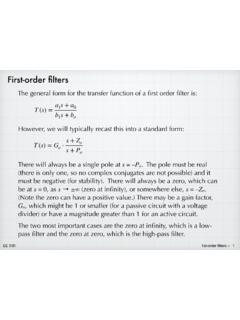
First-order filters
tuttle.merc.iastate.eduLow-pass filter circuits: non-inverting op amp Note: It might slightly disingenuous to treat this as if it were some new type of filter — we can readily see that it is a simple RC filter cascaded with a simple non-inverting amp. However, it is still a useful circuit. 9 + (V)= =& =&+ =5 = 5& V+ 5& 9R(V)= + 5 5 9 + (V) non-inverting amp ...

Figure 1. Series RC circuit driven by a sinusoidal forcing ...
ocw.mit.eduSinusoidal Steady State Response of Linear Circuits ... i(t) s vc(t) +-vR(t) (t) Figure 1. Series RC circuit driven by a sinusoidal forcing function Our goal is to determine the voltages vc(t) and the current i(t) which will completely characterize the “Steady State” response of the circuit.