Stator Winding
Found 9 free book(s)
EE 340 Spring 2011 - UNLV
www.egr.unlv.eduthe stator winding. • Field windings are the windings producing the main magnetic field (rotor windings • armature windings are the windings where the main voltage is induced (stator windings) Construction of synchronous machines The rotor of a synchronous machine is a large electromagnet. The
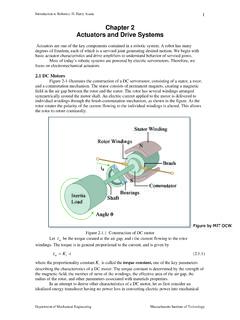
Chapter 2 Actuators and Drive Systems - MIT OpenCourseWare
ocw.mit.eduStator Winding Bearings Shaft Brush Rotor Windings i a N Commutator S Inertia Load Figure by MIT OCW. Introduction to Robotics, H. Harry Asada 2 power. Let E be the voltage applied to the idealized transducer. The electric power is then given
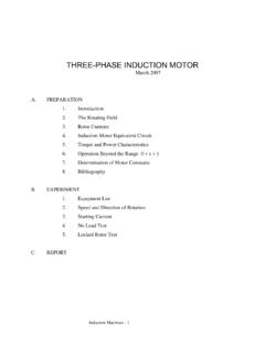
THREE-PHASE INDUCTION MOTOR
classes.engineering.wustl.edumake a DC measurement of stator winding line-to-line resistance using a DMM. 3. Speed and Direction of Rotation . The motor is mounted in a test rig that allows one to control the torque applied to the motor shaft and to measure both rpm and torque. The rpm sensor operates on a Hall effect principle and consists of a disk bearing on its periphery
3-Phase Induction Motors - UNLV
www.egr.unlv.edu: stator and rotor winding resistances • X 1 and X 2: stator and rotor winding leakage reactances • X m: magnetizing reactance • R c: core loss resistance • Rotor winding parameters are referred to the stator side s s m n n n s

CNC- Computer Numeric Control - IIT Kanpur
home.iitk.ac.inThe armature winding is connected to a commutator, which is a cylinder of insulated copper segments ... In an AC servomotor, the rotor is a permanent magnet while the stator is equipped with 3-phase windings. The speed of the rotor is equal to the rotational frequency of the magnetic field of the stator, which is regulated by the frequency ...

Synchronous Machines
www.courses.ece.vt.eduAs the rotor moves within the stator, the field induces voltage in the armature winding of the machine. This voltage is called the generated voltage in a generator and the back EMF in a motor. Its magnitude is directly proportional to the speed of the rotor, the strength of the field, and the effective turns of the armature.

GER-4212 - GE Generator Rotor Design, Operational Issues ...
www.ge.comcuit across the air gap, through the stator core and then back across the air gap into the rotor to complete the loop. Simply stated, the primary function of the field winding is to provide the path for the DC current needed to magnetize the field. However, reach-ing this goal is …

UNIT 1 CHARACTERISTICS OF ELECTRICAL DRIVES Speed ...
bharathuniv.ac.inwinding torque. 3. Torque required to do useful mechanical work (Tm) ... same direction as that of the stator magnetic field, but with a speed greater than the synchronous speed. Such a state occurs during any one of the following process. ...
Operation of Induction Generators.
www.egr.msu.edugenerators are: carbon brushes, slip-rings, rotor and stator. The rotor is an electromagnet made by coiling wires around two or more poles of metal core. The stator is a pair of plates attached to the axle. The brushes are connected to the source of energy and work with the commutator in order to let the induced current flow around the system.