Transformation Diagram
Found 9 free book(s)
Block Diagram Reduction - University of Technology, Iraq
www.uotechnology.edu.iqBlock Diagram Algebra for Branch Point Figure 8: Branch Points . Block Diagram Reduction Rules Table 1: Block Diagram Reduction Rules Table 2: Basic rules with block diagram transformation . Example 1: Example 2: Example 3: Example 4: Example5: ECE 680 Modern Automatic Control Routh’s Stability Criterion June 13, 2007 1
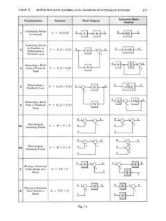
Block Diagram Transformation Theorems - Benard Makaa
www.benardmakaa.com162 BLOCK DIAGRAM ALGEBRA AND TRANSFER FUNCTIONS OF SYSTEMS [CHAP. 7 We do not apply Step 3 at this time, but go directly to Step 4, moving takeoff point 1 beyond block G2 + G,: We may now rearrange summing points I and 2 and combine the cascade blocks in the forward loop using Transformation 6, then Transformation 1: Step 3: Finally, we apply …

WRC-1992 Constitution Diagram for Stainless Steel Weld ...
files.aws.orgferrite, as predicted by the diagram, al though Mn does stabilize austenite in its low-temperature transformation to martensite. Also, the Schaeffler diagram makes its predictions in terms of "per cent ferrite." Later, this was found to be imprecise and the magnetically based "Ferrite Number" (FN) unit was devel

IRON CARBON PHASE DIAGRAM - Higher Technological …
www.hti.edu.egtransformation in relation to Fe-C diagram In order to understand the transformation processes, consider a steel of the eutectoid composition. 0.8% carbon, being slow cooled along line x-x‘. At the upper temperatures, only austenite is present, with the 0.8% carbon being dissolved in solid solution within the FCC. When the steel cools through ...
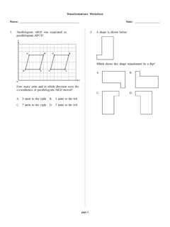
Transformations Worksheet Name: Date
www.matermiddlehigh.orgDec 06, 2016 · Which transformation could be used to show that gure A is congruent to gure B? A. add 5 to each x-coordinate B. multiply each y-coordinate by 1 ... diagram of the park with the placement of the softball diamond is shown below. The position of the baseball diamond will be determined by the re

Chapter 4 Normalization - Villanova
www.csc.villanova.edu1. Develop a diagram that shows the functional dependencies in the SHIPMENT relation. 2. In what normal form is SHIPMENT? Why? 3. Convert SHIPMENT to 3NF if necessary. Show the resulting table(s) with the sample data presented in SHIPMENT. Insertion anomaly? Deletion anomaly? Modification anomaly? 31

Employee Management System - DiVA portal
lnu.diva-portal.orgtransformation into useful information; computer hardware and software are designed and used [2]. A particular case is the Human Resources Information System development. This kind of systems are responsible for storing data of the staff within …
Chapter 15 Mixed Models - Carnegie Mellon University
www.stat.cmu.eduthat just like in regression analysis use of transformation of the outcome or a quantitative explanatory variable, i.e., a covariate, will allow tting of curves.) As usual, you must put a quantitative outcome variable in the \Dependent Variable" box. In the \Factor(s)" box you put any categorical explanatory variables (but not

FE Review Mechanics of Materials - Auburn University
www.eng.auburn.eduFE Mechanics of Materials Review r T Tr J τ= τ= shear stress, force/length^2 T = applied torque, force·length r = distance from center to point of interest in cross-section (maximum is the total radius dimension) J = polar moment of inertia (see table at end of STATICS section in FE review manual), length^4 TL JG φ= φ= angle of twist, radians L = length of shaft