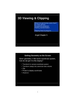
3D Viewing & Clipping
– lines are projected by projecting end points only F Image World I W Note: Since we don’t want the image to be inverted, from now on we’ll put F behind the image plane. Note: Since we don’t want the image to be inverted, from now on we’ll put F …
Download 3D Viewing & Clipping

Information
Domain:
Source:
Link to this page:
Documents from same domain

15-463: Computational Photography
graphics.cs.cmu.eduFraming “Photography is all about framing. We see a subject --and we put a frame around it. Essentially, that is photography when all is said and done.”

Questions on Assignment 1? - Computer graphics
graphics.cs.cmu.edu6 Linear and Affine Maps • A function (or map, or transformation) F is linear if for all vectors A and B, and all scalars k. • Any linear map is completely specified by its effect on a set of basis
Lighting and Shading - Carnegie Mellon Computer Graphics
graphics.cs.cmu.edu–real-time color 3D graphics is feasible –any scheme for describing color requires only three values –lots of different color spaces--related by 3x3 matrix transformations. 21 Color Spaces • There are many ways to describe color –Spectrum • …
Related documents
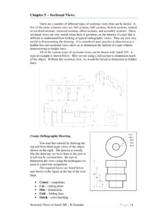
Chapter 5 – Sectional Views
www.unm.eduProj – projection lines The exterior features of the object are dimensioned in the front view but the interior details are not. Dimensioning the interior ... the Pick Points icon on the extreme left of the ribbon. After you have clicked on the “Pick Points” icon, click in the area of the drawing ...

Lecture 2 Introduction to GIS (Based on lecture notes of ...
sites.bsyse.wsu.eduAn equidistant projection maintains consistency of scale for certain distances. An azimuthal projection retains certain accurate directions. Cartographers often use a geometric object to illustrate how a map projection can be constructed. For example, by placing a cylinder tangent to a lighted globe, a projection can be made by tracing the lines of
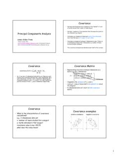
Covariance Covariance Matrix
www.cse.psu.eduas diagonal dotted lines on the plot. •Note they are perpendicular to each other. •Note one of the eigenvectors goes through the middle of the points, like drawing a line of best fit. •The second eigenvector gives us the other, less important, pattern in the data, that all the points follow the main line, but are off to the side of the
Three-Dimensional Coordinate Systems
www.math.usm.eduPlotting Points in xyz-space Graphing in xyz-space can be di cult because, unlike graphing in the xy-plane, depth perception is required. To simplify plotting of points, one can make use of projections onto the coordinate planes. The projection of a point (x;y;z) onto the xy-plane is obtained by connecting the point to

Lines and Planes in R3
people.math.harvard.eduLines and Planes in R3 A line in R3 is determined by a point (a;b;c) on the line and a direction ~v that is parallel(1) to the line. The set of points on this line is given by fhx;y;zi= ha;b;ci+ t~v;t 2Rg This represents that we start at the point (a;b;c) and add all scalar multiples of the vector ~v.
The Geometry of Perspective Projection
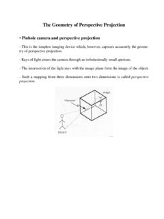
www.cse.unr.eduThe Geometry of Perspective Projection • Pinhole camera and perspective projection-This is the simplest imaging device which, however, captures accurately the geome-try of perspective projection. ... *the vanishing points of all the lines that lie on the same plane form thevanish-
OF POINTS, LINES & PLANES
www.iitg.ac.in75mm on both lines. Name those points b 1 ´ and b respectively. 4) Draw horizontal component of TL a b 1 from point b 1 and name it 1. (the length a-1 gives length of FV as we have seen already) 5) Extend it up to locus of a and rotating a’as center locate b´ as shown. Join a´ b´ as FV. 6) From b´ drop a projector downward & get point b ...
ME 111: Engineering Drawing
www.iitg.ac.inProjection of a line • Obtained by projecting its end points on planes of projections and then connecting the points of projections. • The projected length and inclination of a line, can be different compared to its true length and inclination.

ISOMETRIC PROJECTION - KTU NOTES
www.ktunotes.inAll lines parallel to axes 1, 2 and 3 are isometric lines. 2 3 1 120º The isometric lines are angled at 30º. The lines not parallel to axes 1, 2 and 3 are non-isometric lines. The sides of the cube and all planes parallel to them are isometric planes. Axes 1, 2 and 3 form 120º angles between one another. The projection is isometric