6 Basic Pneumatic System Components - Gears EdS
GEARS-IDS™ kit has a bore (Interior diameter) of 16 millimeters or 0.629”. Since 5/8” = 0.625, this cylinder can also be referred to as a 5/8” bore cylinder for computational purposes. When pressure is applied to the piston, the cylinder rod extends outward 25.4 millimeters or 1.0”. Important values to consider when
Download 6 Basic Pneumatic System Components - Gears EdS

Information
Domain:
Source:
Link to this page:
Documents from same domain

Pressure in Pneumatic Systems - Gears Educational …
www.gearseds.comGEARS Educational Systems 105 Webster St. Hanover Massachusetts 02339 Tel. 781 878 1512 Fax 781 878 6708 www.gearseds.com 1 Pressure in Pneumatic Systems
Designing and Drawing a Sprocket - Gears EdS
www.gearseds.comGEARS Educational Systems 105 Webster St. Hanover Massachusetts 02339 Tel. 781 878 1512 Fax 781 878 6708 www.gearseds.com 1 Designing and Drawing a Sprocket
Lesson 3 Understanding and Using DC Motor …
www.gearseds.comGEARS Educational Systems 105 Webster St. Hanover Massachusetts 02339 Tel. 781 878 1512 Fax 781 878 6708 www.gearseds.com 2 Abstract Engineering design success depends in great part on reducing the time spent creating modules,
Spur Gear Terms and Concepts - Gears EdS
www.gearseds.com3 GEARS Educational Systems 105 Webster St. Hanover Massachusetts 02339 Tel. 781 878 1512 Fax 781 878 6708 www.gearseds.com Gear Terms and Types
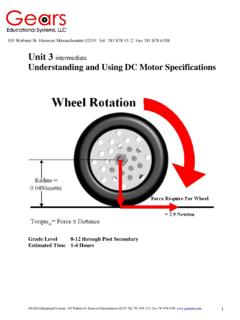
Unit 3 intermediate Understanding and Using DC …
www.gearseds.comGEARS Educational Systems 105 Webster St. Hanover Massachusetts 02339 Tel. 781 878 1512 Fax 781 878 6708 www.gearseds.com 1 Unit 3 intermediate Understanding and Using DC Motor Specifications

Gears SolidWorks Samples 6-13
www.gearseds.comDEPCO llc 800.767.1062 | www.depcollc.com | © 2013 3305 Airport Drive | Pittsburg, KS 66762 M1 Perimeter, Area and Volume Activity Describing and Visualizing Totally ...

Two (12 volt) Batteries in Parallel, One (12 volt) …
www.gearseds.comTwo (12 volt) Batteries in Parallel, One (12 volt) Charger Figure 9: Two Batteries in Parallel, One Charger Batteries connected in series strings can also be recharged by a single charger having the same nominal charging voltage …
6 Basic Pneumatic System Components - Gears EdS
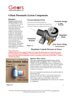
www.gearseds.com1 105 Webster St. Hanover Massachusetts 02339 Tel. 781 878 1512 Fax 781 878 6708 www.gearseds.com Copyright GEARS Educational Systems 2005 6 Basic Pneumatic System Components

Reading Pneumatic Schematic Symbols
www.gearseds.comReading Pneumatic Schematic Symbols A B EA P EB 5/2 Valve has 5 ports and 2 possible conditions 1.) B is pressurized and A is exhausted. 2.) …

2.5 Chain drive systems - Gears EdS
www.gearseds.com© 2002 GEARS Educational Systems 105 Webster St. Hanover Massachusetts 02339 Tel. 781 878 1512 www.gearseds.com 5 Chain Size (Pitch) Chains are sized according to ...
Related documents

TOOL WEAR, TOOL LIFE, HAND TOOLS AND MACHINE ... - IIT …
home.iitk.ac.inTool wear Index, feed marks and surface finish Type of wear depends MAINLY on cutting speed •If cutting speed increases, predominant wear may be “CRATER”wear else “FLANK”wear. • Failure by crater takes place when index h k reaches 0.4 value, before flank wear limit2of h f =1mm for carbide tools is attained.

A 500 HP 390 budget motor??? Read on as we build a…
www.fepower.netwith the dial bore gauge showed the bores were slightly egg shaped, so the block was align honed. Decking the block starts by bolting this reference bar into the block’s main saddle, to provide an index to the crank centerline. the block, indexing the crank centerline and the cam centerline. The 45 degree flats
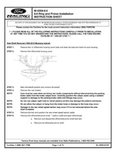
M-4209-8.8 8.8 Ring and Pinion Installation INSTRUCTION …
performanceparts.ford.comUse this as a reference to compare with shim gauge reading prior to installing rear axle pinion bearing. ... Install Dial Indicator with Bracketry TOOL-4201-C or equivalent. Check and note differential case runout. ... bore at any point around the pinion bearing cup, the pinion bearing cup is not properly seated. ...

PUBLIC AUCTION
www.aagauction.comMar 03, 2022 · C-Axis, 4000 Spindle RPM, 30-3000 Live RPM, 2.83” Thru Spindle Bore, Parts Catcher, S20 Collet Pad Spindle Nose, Coolant. Hardinge Cobra 65 CNC Turning Center s/n C65-120 w/ Fanuc Series 21-T Controls, 12-Station Turret,Kennametal KM40 Loc-Block Turret Tooling, 10” 2-Jaw Power Chuck, CoolJet 70-30 Coolant System.

SKF HMV / HMVC
www.skf.comease in itting bearings with a tapered bore and can be used for SKF spherical roller bearings, SKF CARB®, and some SKF self-aligning ball bearings. To be able to use the method, you will need a pump with a highly accurate digital pressure gauge and a dial indicator (ig. 9). Pumps with the sufix DU are supplied with a digital gauge reading from

Dial Indicators/Dial Test Indicators - Mitutoyo
www2.mitutoyo.co.jpTrue measurement = dial reading x compensation value Examples If a 0.200mm measurement is indicated on the dial at various values of θ, the true measurements are: For θ=10˚, 0.200mm×.98=0.196mm For θ=20˚, 0.200mm×.94=0.188mm For θ=30˚, 0.200mm×.86=0.172mm Dial Test Indicator B7533-1990 (Extract from JIS/Japanese Industrial Standards)