7. COOLING TOWER
cooling tower performance. Other factors, which we will see, must be stated along with flow rate m3/hr. For example, a cooling tower sized to cool 4540 m 3/hr through a 13.9°C range might be larger than a cooling tower to cool 4540 m3/hr through 19.5°C range. Range Range is determined not by the cooling tower, but by the process it is serving.
Download 7. COOLING TOWER

Information
Domain:
Source:
Link to this page:
Documents from same domain
4. HVAC AND REFRIGERATION SYSTEM
beeindia.gov.in4. HVAC AND REFRIGERATION SYSTEM Bureau of Energy Efficiency 71 Syllabus HVAC and Refrigeration System:Vapor compression refrigeration cycle, Refrigerants, Coefficient of performance, Capacity, Factors affecting Refrigeration and Air conditioning
4. MATERIALAND ENERGY BALANCE
beeindia.gov.in4. MATERIALAND ENERGY BALANCE Syllabus Material and Energy balance:Facility as an energy system, Methods for preparing process flow, Material and energy balance diagrams. Material quantities, as they pass through processing operations, can be described by material balances. Such balances are statements on the conservation of mass.

1. ENERGY PERFORMANCE ASSESSMENT OF BOILERS
beeindia.gov.inmust be set up on the boiler-house floor. Samples must be taken and bagged throughout the test, the bags sealed and sent to a laboratory for analysis and calorific value determi-nation. In some more recent boiler houses, the problem has been alleviated by mounting the hoppers over the boilers on calibrated load cells, but these are yet uncommon.

List of Architects
beeindia.gov.inArchitects, Interior Designers 7, Malka Ganj, Opp. Hans Raj College, New Delhi New Delhi Tel: +91-11-27457241 +91-11-23857061 +91-11-23857824 Fax: +91-11-23859089 Email: spaceace.india@gmail.com 4. The Energy & Resource Institute (TERI) Darbari Seth Block IHC Complex, Lodhi Road New Delhi New Delhi Tel: +91-11-24682100 +91-11-41504900 extn.2139
6. PUMPS AND PUMPING SYSTEM
beeindia.gov.in6. Pumps and Pumping System Bureau of Energy Efficiency 115 Figure 6.5 Friction Head vs. Flow Figure 6.3 Static Head Figure 6.4 Static Head vs. Flow Friction head (sometimes called dynamic head loss) is the friction loss, on the liquid being moved, in pipes, valves and equipment in the system. Friction tables are universally available for
4 FURNACES - Bureau of Energy Efficiency
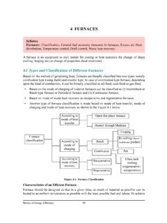
beeindia.gov.in• A refractory chamber constructed of insulating materials for retaining heat at the high operating temperatures. ... • Water cooling energy losses from the skids and stock supporting structure in top and ... Bureau of Energy Efficiency 93 Figure 4.4 Pusher Type Furnaces
Transmission and Distribution Losses (T&D Losses)
beeindia.gov.inThe technical losses are due to energy dissipated in the conductors , transformers and other equipments used for transmission, transformation, sub-transmission and distribution of power. These technical losses are inherent in a system and can be reduced to a certain level.
1. ELECTRICAL SYSTEM - Bureau of Energy Efficiency
beeindia.gov.inA typical plant single line diagram of electrical distribution system is shown in Figure 1.3 Efficiency ranges 28 – 35 % with respect to size of thermal plant, age of plant and capacity utilisation Step-up to 400 / 800 kV to enable EHV transmission Envisaged max. losses 0.5 % or efficiency of 99.5 % EHV transmission and substations at 400 kV ...

ENERGY
beeindia.gov.incode, ECBC 2017. I congratulate the Bureau of Energy Efficiency and the Ministry of Power on the launch of ECBC 2017. India is in a massive construction phase and the code can be a transformative tool for integrating energy efficient design and technologies in all new commercial buildings. U.S. Agency for International Development American Embassy

Energy Conservation Building Code-2017
beeindia.gov.in• For qualifying as a cool roof, roofs with slopes less than 20°shall have an initial solar reflectance of no less than 0.60 and an initial emittance no less than 0.90. • Solar reflectance shall be determined in accordance with ASTM E903-96 and emittance shall be determined in accordance with ASTM E408-71 (RA 1996).
Related documents

WORKING PRINCIPLE OF COOLING TOWER PDF
www.coolingtowerproducts.coman overview of cooling tower types to help you figure out which tower is right for your industrial application and what replacement parts you might need. Back to top Crossflow Cooling Towers Flow Diagram In crossflow cooling tower systems the water vertically flows through the fill media while the air horizontally flows across the falling water.

Cooling Tower Basics and Common Misconceptions2
www.kgogroup.comthe cooling tower. The number 500 is a constant, therefore is independent of the cooling tower. The circulating water flow is determined by the number of pumps running and the pressure drop in the overall circulating water system. Therefore, it likewise is independent of the cooling tower.
Cooling Tower Pumping and Piping - Xylem Applied Water
documentlibrary.xylemappliedwater.comFor the tower piping circuit, the pump must overcome the piping flow friction loss; piping, condenser, cooling tower losses, and valves. It must also provide the energy head necessary to raise water from a low to a higher static head level. …
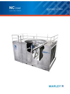
COOLING TOWER
spxcooling.comThe cooling tower must be located at such distance and direction to avoid the possibility of contaminated discharge air being drawn into building fresh air ... flow velocity—such as the cold water basin—sedimentary deposits can provide a breeding ground for bacteria.

The Cooling Water Handbook - Buckman
www.buckman.comThis system sends cooling water out of the equipment and into a pond or cooling tower, which is open to the atmosphere . Here evaporation occurs, removing heat along with the evaporated water . As a result, the remaining water cools . It is then combined with makeup water, which replaces the evaporated water, and is sent through the system again .

Cooling Tower - CED Engineering
www.cedengineering.comA Cooling Tower is a heat rejection device that extracts waste heat to the atmosphere by cooling a stream of hot water in the tower. This type of heat rejection ... approximately 1% of the flow for each 10ºF drop in temperature. The heat from the water stream transferred to the air stream raises the air's temperature and its
COOLING TOWERS - University of Alabama
www.me.ua.eduin Counterflow Cooling Tower steady-state system, the range is the same as the water temperature rise through the load heat exchanger, provided the flow rate through the cooling tower and heat exchanger are the same. Accordingly, the range is determined by the heat load and water flow rate, not by the size or thermal capability the cooling tower.
Condenser Water Temperature Control - Trane
www.trane.com† May vary cooling tower flow below the tower flow limit. 3. Chiller Bypass Figure 4, p. 9 illustrates this system design option. Using the chiller bypass to reduce condenser water flow through the chiller rais es the temperature differential ( ΔT) across the co ndenser which, in turn, maintains the condenser refrigerant pressure. Advantages ...