
A3144 Hall Effect Sensor - Components101
Oct 31, 2005 · hall-effect switches for high-temp. operation www.allegromicro.com supply current 10 15 20 25 supply voltage in volts 0 dwg. gh-041-1 5 supply current in ma 0 2.0 4.0 6.0 8.0 10 b ≥ b op b ≤ b rp t = +25a °c 0 25 50 75 100 ambient temperature in °c-50 dwg. gh-039-1-25 125 v = 8 vcc supply current in ma 7.0 6.0 5.0 4.0 150 b ≤ b rp b ≥ ...
Download A3144 Hall Effect Sensor - Components101

Information
Domain:
Source:
Link to this page:
Documents from same domain
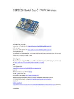
ESP8266 Serial Esp-01 WIFI Wireless - Components101
components101.comESP8266 integrates the most critical components on the board, including power management components, TR switch, RF balun, a peak power of + 25dBm of PA, therefore, ESP8266 only guarantee the lowest BOM cost, and easy to be embedded in any system. ESP8266 BOM is the only external resistors, capacitors, and crystal. ...

Temperature and Humidity Module - Components101
components101.comDHT11 digital temperature and humidity sensor is a calibrated digital signal output of the temperature and humidity combined sensor. It uses a dedicated digital modules capture technology and the temperature and humidity sensor technology to ensure that products with high reliability and excellent long-term stability.

0A-ESP8266 Datasheet EN v4.3
components101.comswitches, RF balun, power amplifier, low noise receive amplifier, filters, power management modules, it requires minimal external circuitry, and the entire solution, including front-end module, is designed to occupy minimal PCB area.

ESP-12E WiFi Module
components101.comWi-Fi Modem circuit can be turned off and CPU suspended to save power according to the 802.11 standard (U-APSD). E.g. in DTIM3, to maintain a sleep 300ms-wake 3ms cycle to receive AP’s Beacon packages, the current is about 0.9mA. Deep-Sleep does not require Wi-Fi connection to be maintained. For application with long time lags between data

NTC Thermistors - Components101
components101.comHIGH-TEMPERATURE SENSORS NTCSMELFE3 and NTCLG100E2 This range of high-quality glass-encapsulated NTC temperature sensors are price-competitive for general use. Not only can theleaded sensor be used at up to 300 °C, but their glass encapsulation makes them ideal for use in corrosive atmospheres and hars h environments. This makes

HC-05 - Components101
components101.comHC-05 Bluetooth module iteadstudio.com 06.18.2010 1 Tech Support: info@iteadstudio.com HC-05 -Bluetooth to Serial Port Module Overview HC-05 module is an easy to use Bluetooth SPP (Serial Port Protocol) module, designed for
Raspberry Pi Pico Datasheet - Components101
components101.comPower Supply (SMPS) power control and sensing the system voltages. Pico has been designed to use either soldered 0.1" pin-headers (it is one 0.1" pitch wider than a standard 40-pin DIP package) or can be used as a surface mountable 'module', as the user IO pins are also castellated. There are SMT pads
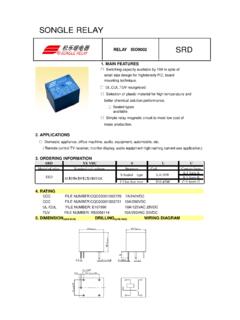
SONGLE RELAY RELAY ISO9002 SRD - Components101
components101.com1 SONGLE RELAY RELAY ISO9002 SRD 1. MAIN FEATURES ᄋ Switching capacity available by 10A in spite of small size design for highdensity P.C. board mounting technique. ᄋ UL,CUL,TUV recognized. ᄋ Selection of plastic material for high temperature and better chemical solution performance. ᄋ Sealed types available.

Pt100-Temperature-Sensors Type TF101
components101.comquick sensor, only suitable for further treatment. Notice: do not cut the sensor leads. Thermal response time refer to manufac-turer data: T 0,9 in the air 10 s, in water <1 s. Order number: 019061 Platinum resistance temperature sensor on ceramic substrate pro - tected by a heat-shrinkabel sl eeve and with PTFE isolated stranded wire.

L298N Motor Driver Datasheet - Components101
components101.comControlling Stepper Motor . In this example we have a typical . NEMA-17 stepper motor with four wires: The key to successful stepper motor control is identifying the wires - that is which one is which. You will need to determine the A+, A -, B+ and B - wires. With our example motor these are red, green, yellow and blue. Now let's get the wiring ...
Related documents
AN885, Brushless DC (BLDC) Motor Fundamentals
ww1.microchip.comNote: Hall Effect Theory: If an electric current carrying conductor is kept in a magnetic field, the magnetic field exerts a trans-verse force on the moving charge carriers which tends to push them to one side of the conductor. This is most evident in a thin flat conductor. A buildup of charge at
Hall Effect Sensing and Application
sensing.honeywell.comTheory of the Hall Effect When a current-carrying conductor is placed into a magnetic field, a voltage will be generated perpendicular to both the current and the field. This principle is known as the Hall effect. Figure 2-1 illustrates the basic principle of the Hall effect. It …

49E Hall-Effect Linear Position Sensor
p.globalsources.com49E Hall-Effect Linear Position Sensor. 1. General Description. The 49E Series Economical Linear Hall-effect sensors are small, versatile linear Hall-effect devices that are operated by the magnetic field from a permanent magnet or an electromagnet. ... Single current sourcing output Linear output for circuit design flexibility

Hall Effect Experiment Manual
d2n0lz049icia2.cloudfront.netThe Hall Effect is the production of a voltage difference (the Hall voltage) across an electrical conductor, transverse to an electric current in the conductor and a magnetic field perpendicular to the current. It was discovered by Edwin Hall (1855-1938) in 1879. The Hall effect was discovered in 1879 by Edwin Herbert Hall while he was
Hall Effect Measurement: Hall Bar and Van der Pauw Geometry
xiaoshanxu.unl.eduMay 20, 2016 · Hall Effect Measurements Hall effect measurements commonly use two sample geometries: Long, narrow Hall bar geometries and Nearly square or circular van der Pauw geometries. Each has advantages and disadvantages. In both types of samples, a Hall voltage is developed perpendicular to a current and an applied magnetic flux.
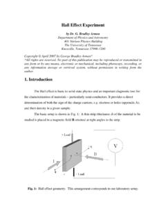
Hall Effect Experiment - University of Tennessee
www.phys.utk.edumaterial in which a current I is flowing, as shown in Fig. 3. Fig. 3: Hall effect geometry again; the strip has a thickness δ, length l, and height h. Here, the applied field B is directed only in the z direction (into the paper). The x-component of E drives the steady current I in the x direction, and a y-component of E

Hall Effect Devices - Lintronics Tech
lintronicstech.comHall Effect Review Edwin Herbert Hall discovered the Hall effect in 1879 while working on his doctoral thesis in physics. In 1880, full details of his experimentation were published in The American Journal of Science and in The Philosophical Magazine. According to the Hall effect, a particle with charge Q at velocity V, moving
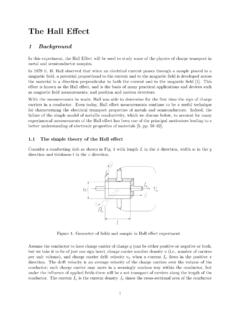
Hall Effect - University of Washington
courses.washington.eduThe Hall Effect 1 Background In this experiment, the Hall Effect will be used to study some of the physics of charge transport in metal and semiconductor samples. In 1879 E. H. Hall observed that when an electrical current passes through a sample placed in a