
Back to Basics - Gear Design
There have been many other types of gear tooth forms, some related to the involute curve, One particular type of recent interest is the "circular arc" gear {where the profile is an arc from the circumference of a.circle}. Pirst proposed in t.his country by Ernest Wildhaber in 'the 1920's, the circular arc gear was recently introduced by the ...
Download Back to Basics - Gear Design

Information
Domain:
Source:
Link to this page:
Documents from same domain

High-Temperature Testing of Stanyl Plastic Gears: A ...
www.geartechnology.comGenerate high-temperature fatigue data for various Stanyl tensile bars at the same temper- ature. 3. Incorporate the influence of tooth bending on the root ... Tensile bar fatigue testing. The tensile bar fatigue tests were run on standard ISO 527-1A injection molded specimens. The specimens were sub-

Product News - March/April 2018 Gear Technology
www.geartechnology.comMitutoyo America Corporation RELEASES MICAT PLANNER VERSION 1.5 Mitutoyo America Corporation recently announced the release of MiCAT Planner v1.5 for the company’s coordinate measur-ing machines. In as little as one click, MiCAT Planner auto-mates the generation of measurement programs based on CAD

Don’t Get Burned - Gear Technology
www.geartechnology.comfeature DON’T GET BURNED. late. You have to have your own lab, and customers need to make sure they’re going to a heat treat with a lab and an experienced staff who knows how to use it. This could save several days. Q: What specifications and/or certifications do you
New ANSI/AGMA Accuracy Standards for Gears
www.geartechnology.comupon local standards, such as AGMA, DIN, JIS, BGA, etc., to internation- al adoption of ISO standards, which are now positioned to become the default specifications for global commerce in gear products.
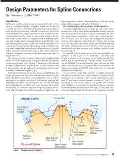
Design Parameters for Spline Connections
www.geartechnology.comIf the splines are being designed, then one of the preferred pres-sure angles from the standards should be used. ANSI and DIN offer the choice between 30°, 37.5° and 45°. In the JIS standard also a pressure angle of 20° is proposed. If the spline is designed for an aftermarket product (for example the sprocket shown Fig. 7), then a simple ...

Gear Technology magazine, The Journal of Gear ...
www.geartechnology.comGear Technology magazine, The Journal of Gear ...

Gear Inspection and Measurement
www.geartechnology.commethod, the master gear and work: gear are mounted on fixed center distance with back-lash. (See Fig. 10.) The master gear drives the work gear. The relative angular rotation of the master and the work are compared and charted. This method can find the same errors as the dual flank: method and can al 0 detect angular velocity errors. Ana]ytica ...

Involute Spline Size Inspection - Gear Technology
www.geartechnology.comthe intereoupling of motors with gear boxes or other loads. Since there is no l10lling action between the mating members. as there is between meshing gears. aU of the spline teeth are expected Ito fit together. AI.though various internal andexter:nal fits are available, the final goal of involute splines isto achieve a self centering con-

Gear Hardness Technology
www.geartechnology.combetween AfSI 4140, a leanalloy steel withpoor hardenability, and AI;S~4340. a rich alloy steel. In order to compare the hardenability of a material. end quench (Jominy) values are widely used as an indicator of a steel's hardenability, Since the quench is so critical to the resulting microstructure, it is necessary to verify the results with an ...

A Comparison of Current AGMA, ISO and ... - Gear Technology
www.geartechnology.comgrally geared centrifugal compres-sors did not exist at that time. The 2002 seventh edition expanded the scope to cover Integrally Geared Centrifugal Compressors and Expander-compressors. It is now essentially three standards pack-aged as one. Each section has its own set of annexes, and for integrally geared cen-
Related documents
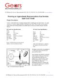
Drawing an Approximate Representation of an Involute …
gearseds.comSpur Gear Tooth Project Description Create a solid model and a working drawing of the 24 pitch gears specified below. It is only necessary to create an approximation of the gear tooth form. These models can be used in both virtual and actual mechanical assemblies that you design an build using the GEARS-IDS kit. The figure on the left is an ...

Journeys Spelling Lists 4th Grade - Mrs. Campbell's Class
campashl3rdgraded91.weebly.comtooth Challenge Words bulletin, cocoon, cushion, proofread, marooned Coming Distractions Lesson 7 Spelling List Week Of: _____ Vowel Sounds /oo/, /oo/ 1. bloom 2. cookbook ... 14. gear 15. hairy 16. compare 17. alarm 18. harsh 19. upstairs 20. square Review Words air, …

Magneto Timing - San Diego Miramar College
faculty.sdmiramar.eduChamfered tooth Timing mark Timing pin Timing gear view hole Installation and Adjustment. Installation and Adjustment • Do not rotate the crankshaft or the magneto until all alignment jigs have been removed. Installation and Adjustment • Each magneto is now installed

Gear Tooth Strength Analysis - Fairfield University
faculty.fairfield.edu2006 by W.H.Dornfeld Tooth Strength: Stresses on Spur Gear Teeth The two primary failure modes for gears are: 1) Tooth Breakage - from excessive bending stress, and 2) Surface Pitting/Wear - from excessive contact stress. In both cases, we are interested in the tooth load, which we got from the torque, T. Recall that we compute the

Spur Gear Terms and Concepts - Gears EdS
www.gearseds.comThe pressure angle figures into the geometry or form of the gear tooth. It refers to the angle through which forces are transmitted between meshing gears. 14.5-degree tooth forms were the original “standard” gear design. While they are still widely available, the 20-degree PA gear tooth forms have wider bases and can transmit greater loads.

MD-12 Spur Gear Design
uni.edu• 20-tooth, 8 pitch, 1-inch-wide, 20° pinion transmits 5 hp at 1725 rpm to a 60-tooth gear. • Determine driving force, separating force, and maximum force that would act on mounting shafts. Example Problem 12-1: Forces on Spur Gear Teeth
Gear Inspection and Measurement
www.geartechnology.comgear. Tooth-fa-tooth composite enol' is the variation of the center distance when the work gear is rotated through an angle of 3601N de-grees, where N is the number of teeth in the work gear. (See Fig..9.) Terms Associated With the Dual Flank …

BoWex Curved-tooth gear coupling - KTR
www.ktr.comCurved-tooth gear coupling ® For continuously updated data please refer to our online catalogue at www.ktr.com Displacements BoWex® couplings are double- cardanic and in addition to transmitting the power compensate for axial, radial and angular shaft displacements in a way to prevent damages from the driving or driven machine, respectively.

Developing the Gear Ratio Formula
www.sae.orgFor every rotation of the 45-tooth gear, the 15-tooth gear must rotate 3 times. This is true no matter how many times the 45-tooth gear rotates. The ratio between the rotations of the 15-tooth driver gear and the 45-tooth driven gear is 3 to 1. That is, the gear ratio is 3 to 1. Using the colon notation, the gear ratio is 3:1.