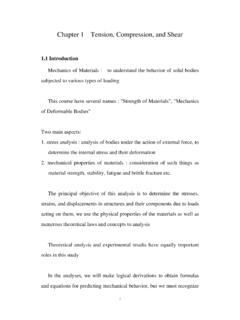
Chapter 1 Tension, Compression, and Shear
stress-strain diagram of materials (compression test are most used for rock and concrete) cylindrical specimen are used ASTM standard specimen for tension test (round bar) d = 0.5 in (12.7 mm) GL = 2.0 in (50 mm) when the specimen is mounted on a testing system (MTS, Instron etc.), the load P and the elongation between GL are measured
Download Chapter 1 Tension, Compression, and Shear

Information
Domain:
Source:
Link to this page:
Documents from same domain

Chapter 9 Deflections of Beams - 首頁
ocw.nthu.edu.tw2 1 d = C = C ! ds the sign convention is pictured in figure slope of the deflection curve dv dv C = tan or = tan-1 C dx dx

LAPLACE TRANSFORM AND ITS APPLICATION IN …
ocw.nthu.edu.twC.T. Pan 1 LAPLACE TRANSFORM AND ITS APPLICATION IN CIRCUIT ANALYSIS C.T. Pan 2 12.1 Definition of the Laplace Transform 12.2 Useful Laplace Transform Pairs

RESPONSE OF FIRST-ORDER RC AND RL CIRCUITS
ocw.nthu.edu.twC.T. Pan 1 RESPONSE OF FIRST-ORDER RC AND RL CIRCUITS C.T. Pan 2 7.1 The Natural Response of an RC Circuit 7.2 The Natural Response of an RL Circuit

Chapter 7 Analysis of Stresses and Strains - 首頁
ocw.nthu.edu.twChapter 7 Analysis of Stresses and Strains 7.1 Introduction axial load " = P / A torsional load in circular shaft $ = T! / Ip bending moment and shear force in beam " = M y / I $ = V Q / I b in this chapter, we want to find the normal and shear stresses acting on ... the stress components for any orientation this is referred as stress ...

Chapter 3 Torsion - 首頁
ocw.nthu.edu.tw3 d& / dx represents the rate of change of the angle of twist &, denote = d& / dx as the angle of twist per unit length or the rate of twist, then max = r in general, & and are function of x, in the special case of pure torsion, is constant along the length (every cross section is subjected to the same torque)

Chapter 5 Stresses in Beam (Basic Topics) - 首頁
ocw.nthu.edu.tw3 5.4 Longitudinal Strains in Beams consider a portion ab of a beam in pure bending produced by a positive bending moment M, the cross section may be of any shape provided it is symmetric about y-axis under the moment M, its axis is bent into a circular curve, cross section mn and pq remain plane and normal to longitudinal lines (plane remains plane can be established by experimental result)
Chapter 3 Torsion
ocw.nthu.edu.tw3 d& / dx represents the rate of change of the angle of twist &, denote = d& / dx as the angle of twist per unit length or the rate of twist, then max = r in general, & and are function of x, in the special case of pure torsion, is constant along the length …
Chapter 9 Deflections of Beams
ocw.nthu.edu.twthe angle of rotation of the axis (also called slope) is the angle between the x axis and the tangent to the deflection curve point m1 is located at distance x ... = C = C = CC ! dx dx2 if the materials of the beam is linear elastic 1 M = C = C [chapter 5] ! EI then the differential equation of the deflection curve is obtained ...
LAPLACE TRANSFORM AND ITS APPLICATION IN CIRCUIT …
ocw.nthu.edu.twThe Laplace transform is an integral transformation of a function f(t) from the time domain into the complex frequency domain, F(s). C.T. Pan 6 12.1 Definition of the Laplace Transform [ ] 1 1 1 ()()1 2 Look-up table ,an easier way for circuit application ()() j st j LFsftFseds j ftFs − + − == ⇔ ∫sw psw One-sided (unilateral) Laplace ...

TIME VARYING MAGNETIC FIELDS AND MAXWELL’S …
ocw.nthu.edu.twD dS vdv Gauss's law . B = 0 S B dS 0 Nonexistence of magnetic monopole x E =-t B L s B dS t E dl Faraday’s Law x H = J + t D L s H dl J dS Ampere's circuit law MAXWELL’S EQUATIONS FOR TIME VARYING FIELDS These are basically four in number. Maxwell's equations in differential form are given by x H = t D + J x E = - t B
Related documents
STRENGTH PROPERTIES OF ROCKS AND ROCK MASSES 1 ...
ceae.colorado.edu2.1 Uniaxial Compression Recall the typical stress strain response curve for a specimen of intact rock under uniaxial compression (see Figure 1 in Lecture Notes 5). Pa rt OA represents the closing of existing cracks in the rock and an overall readjustment of the rock testing machine setup whereas part AB represents the elastic rock response.

Design of Columns
site.iugaza.edu.ps1 Design of Columns Introduction According to ACI Code 2.2, a structural element with a ratio of height-to-least lateral dimension exceeding three used primarily to support compressive loads is defined as column. Columns support vertical loads from the floor and roof slabs and transfer these loads to the footings.

5 CHAPTER 5: TORSION
site.iugaza.edu.pstensile strength of concrete in biaxial tension-compression, taken as 1.06 fc′ , since the tensile strength under biaxial tension is less than that under uniaxial tension. Substituting this in Eq. (5.15), gives the cracking torque Tcr as ( ) cp cp 2 cr c p A T =1.06 f ' (5.16)

Chapter 6: Mechanical properties of metals
courses.washington.edu5 Elastic Shear modulus, G: τ G γ τ= G γ Other elastic properties simple torsion test M M Special relations for isotropic materials: 2(1 +ν) E G = 3(1 −2ν) K = Elastic Bulk modulus, K: pressure test: Init. vol =V o. Vol chg. = ΔV P PP P = - K ΔV V o P ΔV K V o
8. STRENGTH OF SOILS AND ROCKS
people.eng.unimelb.edu.auIn the case of concrete, the compressive strength is the most commonly measured strength parameter and this is also true of rock specimens. For the uniaxial or unconfined compressive strength test a right circular cylinder of the material is compressed between the platens of a testing machine as illustrated in Fig. 8.1. ... The tensile strength ...
Chapter 2 Working Stress and Failure Theories A Simplified ...
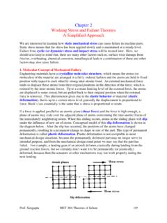
web.njit.eduWhen the external loading is uniaxial, that is S1= a positive or negative real value, S2=S3=0, then all failure theories predict the same as that has been determined from regular tension/compression test. 4.1. Maximum shear stress theory: APPLICABLE FOR DUCTILE MATERIAL – Failure starts by yielding (plastic deformation).
gunt
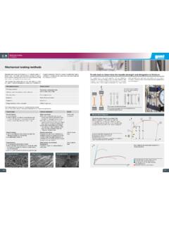
www.gunt.deCompression test to determine fl ow curves Various methods for determining hardness Test process in the compression test 1 thrust plate, 2 specimen, 3 pressure plate, F test load Stress-compression diagram σ stress, ε compression, s 0,2% offset yield point, σ y compression yield stress, σ F compression strength, 1 elastic region, 2 fracture
Rock Mechanics - an introduction for the practical engineer
www.rocscience.comwould initiate under various conditions13 14. Figure 4 illustrates the remarkable agreement between the predicted and observed fracture behaviour of slate specimens subjected to uniaxial compression. It will be noted that the highest strength of slate can be as much as four times its lowest strength,