
Chapter 3 Torsion
3 d& / dx represents the rate of change of the angle of twist &, denote = d& / dx as the angle of twist per unit length or the rate of twist, then max = r in general, & and are function of x, in the special case of pure torsion, is constant along the length …
Download Chapter 3 Torsion

Information
Domain:
Source:
Link to this page:
Documents from same domain

Chapter 9 Deflections of Beams - 首頁
ocw.nthu.edu.tw2 1 d = C = C ! ds the sign convention is pictured in figure slope of the deflection curve dv dv C = tan or = tan-1 C dx dx

LAPLACE TRANSFORM AND ITS APPLICATION IN …
ocw.nthu.edu.twC.T. Pan 1 LAPLACE TRANSFORM AND ITS APPLICATION IN CIRCUIT ANALYSIS C.T. Pan 2 12.1 Definition of the Laplace Transform 12.2 Useful Laplace Transform Pairs

RESPONSE OF FIRST-ORDER RC AND RL CIRCUITS
ocw.nthu.edu.twC.T. Pan 1 RESPONSE OF FIRST-ORDER RC AND RL CIRCUITS C.T. Pan 2 7.1 The Natural Response of an RC Circuit 7.2 The Natural Response of an RL Circuit

Chapter 7 Analysis of Stresses and Strains - 首頁
ocw.nthu.edu.twChapter 7 Analysis of Stresses and Strains 7.1 Introduction axial load " = P / A torsional load in circular shaft $ = T! / Ip bending moment and shear force in beam " = M y / I $ = V Q / I b in this chapter, we want to find the normal and shear stresses acting on ... the stress components for any orientation this is referred as stress ...
Chapter 3 Torsion - 首頁
ocw.nthu.edu.tw3 d& / dx represents the rate of change of the angle of twist &, denote = d& / dx as the angle of twist per unit length or the rate of twist, then max = r in general, & and are function of x, in the special case of pure torsion, is constant along the length (every cross section is subjected to the same torque)

Chapter 5 Stresses in Beam (Basic Topics) - 首頁
ocw.nthu.edu.tw3 5.4 Longitudinal Strains in Beams consider a portion ab of a beam in pure bending produced by a positive bending moment M, the cross section may be of any shape provided it is symmetric about y-axis under the moment M, its axis is bent into a circular curve, cross section mn and pq remain plane and normal to longitudinal lines (plane remains plane can be established by experimental result)
Chapter 9 Deflections of Beams
ocw.nthu.edu.twthe angle of rotation of the axis (also called slope) is the angle between the x axis and the tangent to the deflection curve point m1 is located at distance x ... = C = C = CC ! dx dx2 if the materials of the beam is linear elastic 1 M = C = C [chapter 5] ! EI then the differential equation of the deflection curve is obtained ...
Chapter 1 Tension, Compression, and Shear
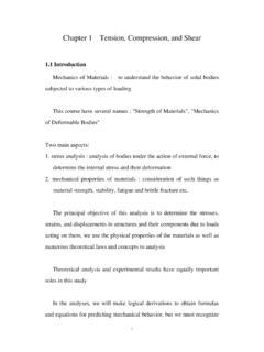
ocw.nthu.edu.twstress-strain diagram of materials (compression test are most used for rock and concrete) cylindrical specimen are used ASTM standard specimen for tension test (round bar) d = 0.5 in (12.7 mm) GL = 2.0 in (50 mm) when the specimen is mounted on a testing system (MTS, Instron etc.), the load P and the elongation between GL are measured
LAPLACE TRANSFORM AND ITS APPLICATION IN CIRCUIT …
ocw.nthu.edu.twThe Laplace transform is an integral transformation of a function f(t) from the time domain into the complex frequency domain, F(s). C.T. Pan 6 12.1 Definition of the Laplace Transform [ ] 1 1 1 ()()1 2 Look-up table ,an easier way for circuit application ()() j st j LFsftFseds j ftFs − + − == ⇔ ∫sw psw One-sided (unilateral) Laplace ...

TIME VARYING MAGNETIC FIELDS AND MAXWELL’S …
ocw.nthu.edu.twD dS vdv Gauss's law . B = 0 S B dS 0 Nonexistence of magnetic monopole x E =-t B L s B dS t E dl Faraday’s Law x H = J + t D L s H dl J dS Ampere's circuit law MAXWELL’S EQUATIONS FOR TIME VARYING FIELDS These are basically four in number. Maxwell's equations in differential form are given by x H = t D + J x E = - t B
Related documents

Fatigue Analysis - UTEP
me.utep.edu•Constant amplitude S-N curves of this type are plotted on semi-log or log-log coordinates. •S-N curves obtained under torsion or bending load-control test conditions often do not have data at the shorter fatigue lives (say 10^3 or 10^4 cycles and less) due to significant plastic deformation.

HOLLOW STRUCTURAL SECTIONS - McGill University
www.cim.mcgill.caC Torsional shear constant of cross-section (in. 3) D Outside diameter of round HSS (in.) h Nominal depth minus 3 times the design wall thickness,t (in.) I Moment of inertia of cross-section (in. 4) Ix Moment of inertia of cross-section about the X-X axis (in. 4) Iy Moment of inertia of cross-section about the Y-Y axis (in. 4)

Torsion of (Thin) Closed Sections - MIT OpenCourseWare
ocw.mit.edutorsional stiffness of ... = constant (we will use the concept of “shear flow ” Analogy: single 1-D pipe flow when we deal with shell beams) uh = constant velocity Returning to

Notes 9 Torsional Vibrations a (twisted) Overview
rotorlab.tamu.eduare no stress reversals (stress is constant with circular orbits) Natural Frequencies Independent of shaft rotating speed. Influenced by shaft rotating speed (gyroscopics and bearings) Excitation Rarely experiences instability (there are exceptions). There is no synchronous (1x) torsional excitation, except from gear pitch line runout.
BEE501- CONTROL SYSTEM UNIT 1 SYSTEMS AND THEIR …
www.bharathuniv.ac.inTorsional spring constant(K) Reciprocal of Capacitance (1c)(1c) Angular Displacement(θ) Charge(q) Angular Velocity(ω) Current(i) Force Current Analogy: In force current analogy, the mathematical equations of the translational mechanical system are compared with the nodal equations of the electrical system.

12 Buckling Analysis - Rice University
www.clear.rice.edutorsional stiffness, G J / L, where J is the polar moment of inertia of the cross‐sectional area (J = Iz = Ix + Iy). Today, stiffness usually refers to the finite element stiffness matrix, which can include all of the above stiffness terms plus general solid or shell stiffness contributions.

Fatigue - Michigan State University
www.egr.msu.eduReversed Torsional Loading reversed biaxial stress distortion energy theory 58% C L=0.58 load factor maximum stresses on surface shear stresses fatigue start. ... constant-life fatigue diagram. Fatigue Strength Juvinall p.312 Fig. 8.12. Fatigue Strength Effect of mean stress

Mathematical Modeling of Systems - Engineering
www.site.uottawa.catorsional spring system with applied torque Ta(t). Assume the torsional spring is massless. Suppose we want to measure the torque Ts(t) transmitted to the mass m. Since the spring is massless, the sum of the torques acting on the spring itself must be zero, or Ta (t) −Ts (t) =0