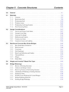
Chapter 5 Concrete Structures Contents
WSDOT Bridge Design Manual M 23-50.20 Page 5-1 September 2020. Chapter 5 Concrete Structures. 5 .0 General. The provisions in this section apply to the design of cast-in-place (CIP) and precast . concrete structures, both reinforced and prestressed. Design of concrete structures shall be based on the requirements and guidance cited
Download Chapter 5 Concrete Structures Contents

Information
Domain:
Source:
Link to this page:
Documents from same domain

Bridge Design Manual M 23-50 Chapter 15 …
wsdot.wa.govChapter 15 Structural Design Requirements for Design-Build Contracts Page 15-2 WSDOT Bridge Design Manual M 23-50.18 June 2018 15.2 Bridge Configuration Criteria
Chapter 5 Concrete Structures Contents
wsdot.wa.govChapter 5 Concrete Structures Contents. ... Bridge Design Engineer, Bridge Construction Office, and Materials Lab. 2. Prestressed Concrete Girders ... Used in CIP post-tensioned concrete box girder construction, deep bridge foundations, or in other special structural applications if significant economy
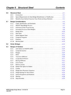
Chapter 6 Structural Steel Contents
wsdot.wa.govWSDOT Bridge Design Manual M 23-50.18 Page 6-1 June 2018 Chapter 6 Structural Steel 6.0 Structural Steel 6.0.1 Introduction This chapter primarily covers design and construction of steel plate and box girder bridge

Salt Spring Island Pender Bellingham
wsdot.wa.govEdmonds Kingston Seattle Bainbridge Fauntleroy Southworth Vashon Tahlequah Point Defiance Bremerton 167 512 90 307 Seattle 230 182 189 177 164 163 132 230 104 250 194 212 154 142 Bay Harbor Townsend Island Gamble Coupeville. Title: Washington State Ferries Route Map Author: Washington State Ferries Created Date:

Mileposts - Washington State Department of Transportation
wsdot.wa.gov5 5 10 5 10 10 30 20 2 0 40 10 20 10 10 1 0 10 30 30 50 20 30 30 30 20 20 2 0 1 0 10 10 10 40 20 10 10 10 10 15 35 10 10 10 10 10 20 20 20 20 20 20 20 20 10 10 10 15 ...

WSDOT Region Milepost Maps 2019
wsdot.wa.gov2 £¤ 195 £¤ 395 £¤ 2 uv 25 uv 21 uv 23 uv 231 uv 261 uv 31 uv 291 uv 27 uv 194 uv 127 uv 904 uv 272 uv 211 uv 206 uv 902 uv 290 uv 263 uv 271 uv 270 uv 292 uv ...

N O R T H C E N T R A L N O R T H W E S T E A S T E R N
wsdot.wa.govlake blaine hoquiam bridgeport yakima okanogan king grant lewis chelan ferry st ev n adams clallam lincoln skagit kittitas pierce whatcom whitman benton jefferson douglas spokane snohomish klickitat skamania pacific mason grays harbor cowlitz franklin pend oreille clark asotin walla walla columbia kitsap thurston island garfield san juan ...

2018-2019 Winter Driving Guide
wsdot.wa.govvehicle and practice installing them. • Studded tires do NOT meet the chain requirement. Even vehicles equipped with studded tires need to carry chains in winter conditions. STUDDED TIRE INFORMATION Washington only allows studded tires from Nov. 1 through March 31. There is no individual exception to the studded tire dates and violators face ...

Chapter 1 Roadway Treatment Goals
wsdot.wa.gov2. During event: Apply deicing chemicals to roadway during a snow event to keep snow and ice from accumulating and bonding to the pavement and to expedite the process of mechanical removal. If compact snow or black ice forms on the roadway, apply pre-wet solid chemicals to break the snow/ice bond and to assist the process of mechanical removal. 3.

2021 Standard Specification M 41-10
wsdot.wa.gov2021 Standard Specifications M 41-10 Page 3 Foreword These Standard Specifications for Road, Bridge, and Municipal Construction have been developed to serve as a baseline for the work delivered to the public by the Washington
Related documents
Roark’sFormulas forStressandStrain
materiales.azc.uam.mxChapter 5 NumericalMethods 73 The Finite-Difference Method. The Finite-Element Method. The Boundary-Element Method. References. Chapter 6 ExperimentalMethods 81 Measurement Techniques. Electrical Resistance Strain Gages. Detection of Plastic Yielding. Analogies. Tables. References. Part3 FormulasandExamples Chapter 7 Tension,Compression,Shear ...
BEAMS SUBJECTED TO TORSION AND BENDING - II
www.steel-insdag.orgBEAMS SUBJECTED TO TORSION & BENDING-II in which () 2 M p LT 1 ME B + + = η φ MP, the plastic moment capacity = fy.Zp / γm Zp = the plastic section modulus ME, the elastic critical moment = where λLT is the equivalent slenderness. m 2 y LT 2 p f M E γ λ π ⋅ 4.3 Applied loading having both Major axis and Minor axis moments

5 CHAPTER 5: TORSION - site.iugaza.edu.ps
site.iugaza.edu.ps5 CHAPTER 5: TORSION 5.1 Introduction If external loads act far away from the vertical plane of bending, the beam is subjected to twisting about its longitudinal axis, known as torsion, in addition to the shearing force and bending moment. Torsion on structural elements may be classified into two types; statically determinate, and
Chapter 9 THE MATERIALS SELECTION PROCESS
faculty1.aucegypt.eduAluminum 6061, T6 temper 93 13.5 2.7 6 1.69 Epoxy+70% glass fibers 70 10.2 2.11 9 2.26 a The working stress is computed from yield strength using a factor of safety of 3.

Extension & Torsion Springs (Chapter 10)
faculty.mercer.eduStress in Torsion Springs The coil of a torsion spring experiences bending stress (despite the name of the spring). Including a stress-correction factor, the stress in the coil can be represented by The stress-correction factor at inner and outer fibers has been found analytically for round wire to be K i is always larger, giving the highest stress at the inner fiber.
Chapter 3 Torsion
web.ncyu.edu.twof the shaft, Torsion formulas: (3.5a) The maximum shear stress τ max is found by replacing ρby the radius r of the shaft: (3.5b) Because Hook´s law was used in the derivation of Eqs. (3.2)-(3.5), these formulas are valid if the shear stresses do not exceed the proportional limit of the material shear. Furthermore, these

17 BEAMS SUBJECTED TO TORSION AND BENDING -I
www.steel-insdag.orgThis couple, which acts to resist the applied torque, is called warping torsion. For the I-section shown in Fig. 5, warping torsion is given by Tw = Vf.h (6) The bending moment in the upper flange is given by Version II 17-6

Chapter 3 Torsion
ocw.nthu.edu.twChapter 3 Torsion 3.1 Introduction Torsion : twisting of a structural member, when it is loaded by couples that produce rotation about its longitudinal axis T1 = P1 d1 T2 = P2 d2 the couples T1, T2 are called torques, twisting couples or twisting moments unit of T: N-m, lb-ft in this chapter, we will develop formulas

STRESS AND DEFORMATION ANALYSIS - Pearson
www.pearsonhighered.com3–5 Deformation under Direct Axial Load 3–6 Shear Stress Due to Direct Shear Load 3–7 Torsional Load—Torque, Rotational Speed, and Power 3–8 Shear Stress Due to Torsional Load 3–9 Torsional Deformation 3–10 Torsion in Members Having Non-Circular Cross Sections 3–11 Torsion in Closed Thin-Walled Tubes
Chapter 5 Stresses In Beams - ncyu.edu.tw
web.ncyu.edu.twChapter 5 Stresses In Beams. 5.1 Introduction In previous chapters, the stresses in bars caused by axial loading and torsion. Here consider the third fundamental loading : bending. Make certain simplifying assumptions. the resulting equations have served well in …