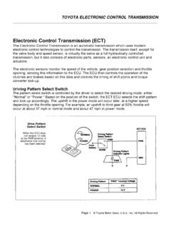
Electronic Control Transmission (ECT)
The throttle position sensor takes the place of throttle pressure in a fully hydraulic control transmission. By relaying the throttle position, it gives the ECU an indication of engine load to control the shifting and lock-up timing of the transmission. There are two types of throttle sensors associated with ECT transmissions. The type is related
Download Electronic Control Transmission (ECT)

Information
Domain:
Source:
Link to this page:
Documents from same domain
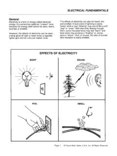
ELECTRICAL FUNDAMENTALS General Electricity is …
autoshop101.comGeneral Electricity is a form of energy called electrical energy. It is sometimes called an "unseen" force because the energy itself cannot be seen, heard,

SHIFT INTERLOCK SYSTEM - Autoshop 101
autoshop101.comSHIFT INTERLOCK SYSTEM The shift lock system is designed to ensure the proper operation of the automatic transmission. The driver must depress the brake pedal in order to move the gear selector from

UNDERSTANDING RELAYS - Automotive Training …
autoshop101.comUNDERSTANDING RELAYS Page 1 © Autoshop101.com, All Rights Reserved. This Automotive Series UNDERSTANDING RELAYS has been developed by
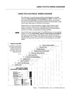
USING TOYOTA WIRING DIAGRAMS USING THE …
autoshop101.comUSING THE ELECTRICAL WIRING DIAGRAM USING TOYOTA WIRING DIAGRAMS Page 1 © Toyota Motor Sales, U.S.A., Inc.All Rights Reserved.

Appendix A Toyota Wiring Diagram Symbols
autoshop101.comToyota Wiring Diagram Symbols. Appendix A A-2 TOYOTA Technical Training IGNITION SWITCH A key operated switch with several positions which allow various circuits to become operational, including the primary ignition circuit. SENSOR (Thermistor) A …

TOYOTA ELECTRONIC TRANSMISSION CHECKS & …
autoshop101.comDiagnosis During diagnosis, always verify the customer complaint. If the verification includes a test drive, be sure to check the level of ATF first. This will ensure that a low level is not contributing to the problem and give you an idea as to the …
Related documents

Logix 5000 Controllers Messages - Rockwell Automation
literature.rockwellautomation.comThe MSG instruction attempts to enter the queue. This time the throttle position is open and the message can pass to the message queue. The EW bit is set. Depending on how you configure a MSG instruction, it may use a connection to send or receive data. This type of message And this communication method Uses a connection CIP data table read or ...

Resetting The Throttle Body Calibration (this step is ...
uprev.comResetting The Throttle Body Calibration (this step is conditional) A Rough Idle or a SES can sometimes be caused by a change in the throttle body position sensor calibration. To correct any accidental changes in throttle body calibration, use these procedures to recalibrate. Note: These procedures are a little tricky to do.
GCV160 • GCV190
cdn.powerequipment.honda.com6. Position the throttle lever for the desired engine speed. For best engine performance, it is recommended the engine be operated with the throttle in the FAST (or high) position. Stopping the Engine 1. Move the throttle lever to the SLOW position and allow the engine to idle for a few seconds. 2. Move the throttle lever to the STOP position. 3.

OWNER’S MANUAL ENGLISH GCV160 • GCV190
cdn.powerequipment.honda.comRemote Throttle STARTING THE ENGINE 1. Move the remote throttle lever* [2] to the FAST position. 2. Move the flywheel brake lever* [3] to the RUN position. 3. Pull the starter grip lightly until resistance is felt; then pull briskly. STOPPING THE ENGINE 1. Move the remote throttle lever* [2] to the SLOW position. 2.

Maintenance Aspects of Owning Your Own Aircraft
www.faasafety.gov• Mixture and throttle controls for operation and ease of movement. • Propeller control for operation and ease of movement. • Engine idle for proper RPM. • Carburetor heat or alternate air. • Alternator output under load (for example, landing light in “on” position). • Vacuum system (if installed) for output.

WOLF BRAND SCOOTERS USER S MANUAL Instructions to Users
cdnmedia.endeavorsuite.com2 Throttle grip: When the engine is on, twist to accelerate. 3 The Cut Off or Run /Stop Switch: Electrical power for the engine is turned on when the switch is set to The position marked “ ” This switch must be set to this position for the engine to start and run

IK0800219 - Accelerator Position Sensor/IdleValidation ...
static.nhtsa.govWhen the pedal is not in the idle position (throttle applied), the IVS supplies a 12V signal to the ECM. The ECM compares APS/IVS inputs at terminals 8 and 27 to verify that the pedal is in the idle position. If the APS signal at terminal 8 indicates throttle is being applied, the ECM expects to see 12V at IVS terminal 27. If the APS

Service Tips Kawasaki Throttle Adjustment
ybravo.comThrottle control on BBC engines. The methods for checking and adjusting RPM and Full Throttle position is the same on all the Kawasaki FJ180V engines. We are illustrating the procedures on the BBC engine for clarity. FJ180V KAI Engine Specifi cations used by Ybravo: “M22” used on 21” Zone Start - 3300 RPM

Adaptive Cruise Control Design draft1p3
sunnyday.mit.eduthrottle control to maintain the vehicle speed at the target speed. 3.5 Operation During Follow Mode (ACC Time Gap Control) The ACC system enters follow mode or 'ACC time gap control' if the radar detects a forward vehicle at or within the clearance distance. During this mode of operation, the ACC system

ELECTRIC CHOKE HOOKUP & ADJUSTMENT
documents.holley.com8. Return the throttle to the fast idle position, as described in step 6. Restart the engine, and recheck the fast idle RPM. Repeat steps 6 & 7 until the desired fast idle RPM is met. Technical Support: 1-866-464-6553 199R11256 Date: 1-19-17