Global Stiffness Matrix For Beams
consists of establishing the stiffness matrix and the load matrix The mostmatrix and the load matrix. The most important matrix generated is the overall joint stiffness matrix [SJ ]. The joint stiffness matrix consists of contributions from the beam stiffness matrix [SM ]. It is convenient to assess the contributions for one typical member i
Download Global Stiffness Matrix For Beams
Information
Domain:
Source:
Link to this page:
Documents from same domain
EMBEDDED SYSTEMS PROGRAMMING WITH THE …
academic.csuohio.edu5 Preface This book is intended for use by Junior-level undergraduates, Senior-level undergraduates, and Graduate students in electrical engineering as well as practicing
THEORIES OF ACCIDENT CAUSATION - Cleveland …
academic.csuohio.eduCleveland State University Work Zone Safety and Efficiency Transportation Center Section 3 Accident Theories THEORIES OF ACCIDENT CAUSATION

The Content Analysis Guidebook - Cleveland State …
academic.csuohio.edu202 The CoNTeNT ANALySIS GUIDeBooK of the Japanese earthquake of 2011, for example, the social media of the world followed and documented the crisis, aided in recovery efforts through

OSHA Subpart R: Steel Erection
academic.csuohio.eduSection 17 1926 Subparts R Cleveland State University Work Zone Safety and Efficiency Transportation Center OSHA Subpart R: Steel Erection
Chapter 9: Column Analysis and Design
academic.csuohio.edu9.1 Chapter 9: Column Analysis and Design Introduction Columns are usually considered as vertical structural elements, but they can be positioned in any orientation (e.g. diagonal and horizontal compression elements in a
THEORIES OF ACCIDENT CAUSATION - …
academic.csuohio.eduCleveland State University Work Zone Safety and Efficiency Transportation Center Section 3 Accident Theories THEORIES OF ACCIDENT CAUSATION

OSHA 1926 Subpart D Occupational Health & …
academic.csuohio.eduSection 9 1926 Subparts D & E Cleveland State University Work Zone Safety and Efficiency Transportation Center 1926.50 Medical Services and First Aid
OSHA Subpart R: Steel Erection - …
academic.csuohio.eduSection 17 1926 Subparts R Cleveland State University Work Zone Safety and Efficiency Transportation Center Before Authorizing The Start Of Steel
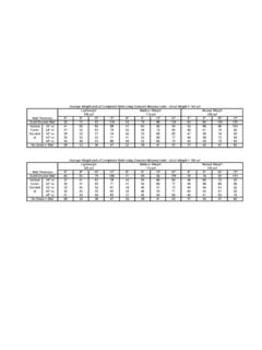
Average Weight (psf) of Completed Walls Using …
academic.csuohio.edu6" 8" 10" 12" 6" 8" 10" 12" 6" 8" 10" 12" 52 75 93 118 58 78 98 124 63 84 104 133 Vertical 16" oc 41 60 69 88 47 63 80 94 52 66 86 103 …

Preliminaries: Beam Deflections Virtual Work
academic.csuohio.eduSection 6: The Flexibility Method - Beams Washkewicz College of Engineering 1 Preliminaries: Beam Deflections –Virtual Work There are several methods available to calculate deformations (displacements and rotations)
Related documents
Beam Stiffness - Memphis
www.ce.memphis.eduBeam Stiffness Example 5 - Load Replacement Consider the beam shown below; determine the equivalent nodal forces for the given distributed load. The work equivalent nodal forces are shown above. Using the beam stiffness equations: 2 2 11 22 11 3 22 22 22 2 12 2 12 12 6 12 6 64 6 2 12 6 12 6 62 6 4 y y wL wL wL wL fvLL m EI LL L L fvLL L m LL L L
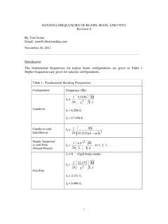
BENDING FREQUENCIES OF BEAMS, RODS, AND PIPES …
www.vibrationdata.comk is the stiffness. The stiffness is thus k = F / y (A-25) The force at the end of the beam is mg. The stiffness at the end of the beam is k mg mgL EI ª ¬ « « º ¼ » » ® ° °° ¯ ° ° ° ½ ¾ ° ° ¿ ° ° 3 3 (A-26) k EI L 3 3 (A-27)
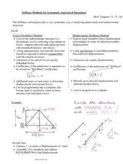
Stiffness Methods for Systematic Analysis of Structures
engineering.purdue.eduStiffness Method for Frame Structures For frame problems (with possibly inclined beam elements), the stiffness method can be used to solve the problem by transforming element stiffness matrices from the LOCAL to GLOBAL coordinates. Note that in addition to the usual bending terms, we will also have to account for axial effects .

Introduction to Stiffness Analysis
web.engr.uky.eduTo illustrate the stiffness method of analysis, we will first consider continuous beam structures. Start off by considering the two-span beam shown in Figure 1. Fig. 1 – Two-Span Continuous Beam 10 1: Determine the degree of kinematic indeterminacy. The only unknown node/joint displacement occurs at node B and it is a rotational displacement.
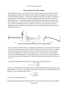
Impact Load Factors - Rice University
www.clear.rice.eduInitial velocity results, without the beam stiffness However, the stiffness of a simply supported beam at the center (load) point was calculated in the second solve (Lightbulb icon pick) from additional rules by inputting the beam properties, length, and load location (centered 0.6 …
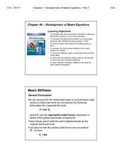
BEAM ANALYSIS USING THE STIFFNESS METHOD
www.erbakan.edu.trStiffness Matrix! General Procedures! Internal Hinges! Temperature Effects! Force & Displacement Transformation! Skew Roller Support BEAM ANALYSIS USING THE STIFFNESS METHOD. 2 Slope ΠDeflection Equations