
Installation Instructions - Painless Performance
a. Connect this wire to the Throttle Position Sensor signal on a “Throttle-By-Cable” engine or an Accelerator Pedal Position Sensor signal on a “Throttle-By-Wire” engine. b. On most GM “Throttle-By-Cable” applications this is the Dark Blue wire at the Throttle Position Sensor connector. c. See Diagram 3 on page 15.
Download Installation Instructions - Painless Performance

Information
Domain:
Source:
Link to this page:
Documents from same domain

Manual #90567 For Installing: Part #30830
www.painlessperformance.com7 Figure 1 C.S.I. Harness Schematic CONTENTS OF THE PAINLESS C.S.I. WIRE HARNESS KIT Refer to the list below to take inventory of all the parts in the kit. If anything is found to be

For Installing: #10127 Customizable Mopar Chassis …
www.painlessperformance.comWire Harness Installation Instructions For Installing: #10127 Customizable Mopar Chassis Harness 21 Circuit Manual #90542

Wire Harness Installation Instructions - Painless …
www.painlessperformance.comWire Harness Installation Instructions For Installing: #20110 Classic Customizable Chevy II/Nova 1966-67 Harness 21 Circuit Manual #90522

Wire Harness Installation Instructions - Painless …
www.painlessperformance.comWire Harness Installation Instructions For Installing: Part #20120 22 Circuit Ford Mustang (1965- 1966) Manual #90526

Wire Harness Installation Instructions - Painless …
www.painlessperformance.comWire Harness Installation Instructions For Installing: #10101 Classic Customizable Harness-GM Keyed Column-21 Circuit #10102 Classic Customizable Harness-Non GM Keyed Column-21 Circuit

175 o OFF THERMOSTAT INSTALLATION …
www.painlessperformance.com1 2501 Ludelle Street Fort Worth, Texas 76105 . 817-244-6212 phone . 817-244-4024 fax . 800-423-9696 Tech . E-Mail: painless@painlessperformance.com . Web: www.painlessperformance.com

Manual #90560 For Installing: #10111 Direct Fit Jeep YJ ...
www.painlessperformance.com7 Sections are divided into subsections and Paragraphs.Throughout these instructions, the Figure numbers refer to pictures and the Diagram numbers refer to illustrations.Figure numbers correspond to the Section number the are covered in. Always pay special and careful

HIGH AMPERAGE ALTERNATOR KIT (140-190 AMPS)
www.painlessperformance.com2 onto the output post of the alternator. This connection can be seen in Figure 1 on the next page and can be accomplished one of two ways: #1 Install each wire separately • Slide the rubber boot and/or a piece of the smaller sized heat shrink onto the wire found in the kit.

Wire Harness Installation Instructions
www.painlessperformance.com3.0 CONTENTS OF THE PAINLESS WIRE HARNESS KIT Refer to the list below to take inventory of all the parts in the kit. If anything is found to be missing, contact the dealer the kit was purchased

80230 - painlessperformance.com
www.painlessperformance.comPainless Performance Limited Warranty and Return Policy Chassis harnesses and fuel injection harnesses are covered under a lifetime warranty. All other products manufactured and/or sold by Painless Performance
Related documents

REPAIRING ALUMINUM WIRING - CPSC.gov
www.cpsc.govthe aluminum wire itself. Depending on the architectural style of your home and the number and locations of unfinished spaces (e.g., basements and attics), it may be relatively easy for a qualified electrician to rewire your home. A new copper wire branch circuit system would be installed, and the existing aluminum wire could be
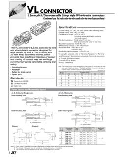
CONNECTOR
www.jst-mfg.com6.2mm pitch/Disconnectable Crimp style Wire-to-wire connectors (Combined use for both wire-to-wire and wire-to-board connections) This VL connector is 6.2 mm pitch wire-to-wire and wire-to-board connector, designed for large current up to 20 A (1 or 2-circuit with 3.5 mm2 wire). Secondary retainer, which

CIRCULAR PLASTIC CONNECTORS - Mouser Electronics
www.mouser.comMIL-C-5015 Style Circular Product Facts • Intermateable with Metal-Shell sizes 20-14 and 18-10, MIL-C-5015 Style connectors •e High impact resistant plastic housing made of UL 94V-0 rated material • ghtgwhtLi i • Lower cost than standard MIL-C-5015 connectors • Industry accepted Type III+ pin and socket contacts, available
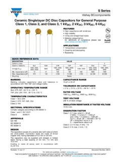
Ceramic Singlelayer DC Disc Capacitors for General Purpose ...
www.vishay.com• Crimp and straight lead styles • Material categorization: ... copper wire, having diameters of 0.6 mm or 0.8 mm. The capacitors may be supplied with straight or kinked ... Style Lead Spacing RoHS-Compliant S series The first two digits are the significant figures of capacitance and