
Manual - Curtis Instruments
The outline and mounting hole dimensions are shown in Figure 2. The controller should be mounted by means of the two mounting holes at the opposing corners of the heatsink, using M4 (#8) screws. Figure 2 Mounting Dimensions, Curtis 1212 and 1212P Controllers. Dimensions in millimeters and (inches)
Download Manual - Curtis Instruments

Information
Domain:
Source:
Link to this page:
Documents from same domain

AC Motor Controller with VCL - Curtis Instruments
cdn.curtisinstruments.comTogether with the Curtis model 3141 CAN LCD display and the user-friendly Curtis Integrated Toolkit, the Curtis model AC F2-A is the ultimate Class III truck control system. FEATURES Fit for Purpose Compact, rugged housing with very small ‘footprint’ for its power rating. Heavy duty M6 busbars for motor and battery connectors.

AC Motor Controller and DC Pump System Controller
cdn.curtisinstruments.comTogether with the Curtis model 3141 CAN LCD display and the user-friendly Curtis Integrated Toolkit, the Curtis model AC F2-C is the ultimate Class III truck control system. FEATURES High efficiency, field-oriented motor control algorithms. Fully integrated Half-bridge hydraulic pump controller that is configurable for various hydraulic

On-Road AC Motor Controller Model 1239E
cdn.curtisinstruments.comReverse polarity protection on battery connections. Short circuit protection on all output drivers. Thermal cutback, warning, and automatic shutdown provide protection to motor and controller. Rugged sealed housing and connectors meet IP65 environmental sealing standards for use in harsh environments. Meets or complies with relevant US
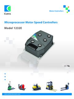
Microprocessor Motor Speed Controllers Model 1232E
cdn.curtisinstruments.comwarranty two year limited warranty from time of delivery. ksi switch 1/ana 1 switch 3 switch 4 switch 5 switch 6 switch 7 switch 8 coil return driver 1 driver 2 driver 3 driver 4 keyswitch encoder battery 24 i/o ground can h serial port switch 2/ana 2 throttle pot high throttle wiper pot 2 wiper pot low j1-24 j1-9 j1-10 j1-11 j1-12 j1-22 j1-33 ...
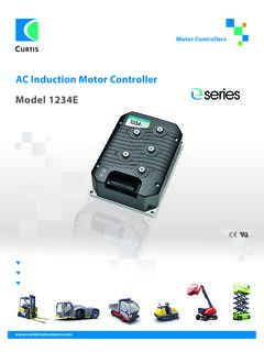
AC Induction Motor Controller Model 1234E - Curtis …
cdn.curtisinstruments.comMotor Braking Torque c Category 2 ≥16 yrs ≥90% Model Battery Voltage Nominal (V) 2 Minute RMS Current Rating (A) S2–60 Min RMS Current Rating 1234E-23XX 24 350 175 1234E-52XX 36–48 275 140 1234E-53XX 36–48 350 175 1234E-62XX 48–80 250 110 Contact Curtis to obtain the VCL Vehicle Control Language compiler and development tools.
SERIES - Curtis Instruments
cdn.curtisinstruments.com6 5 display position encoder b+ u v w b– main j1-31 j1-32 j1-7 j1-26 i/o gnd phase a phase b 1 2 4 3 ac motor switch 16 j1-19 digital driver 6 em rev. load hold valve lower lift mode motor temp. input t +12v (100ma) +5v (100ma) emergency stop wiring diagram 1232 ac induction motor controller pump cont digital driver 7 j1-20 j1-30 analog out ...
Models 1204M/05M/09M/21M - Curtis Instruments
cdn.curtisinstruments.comaluminum extruded housing. 3 Simple mounting and wiring with push-on connectors for control signals. 3 Plated solid copper buses used for all power connections. 3 Thermal protection and compensation circuit provides ... (#18 AWG) vinyl insulated stranded wire
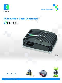
AC Induction Motor Controllers - Curtis Instruments
cdn.curtisinstruments.comforward reverse throttle pot pot 2 pv driver j1-2 can term h j1-21 j1-34 can term l short for 120 pot 2 ohm termination high j1-27 prop. valve 8 6 5 display speed encoder b+ u v w b– main j1-31 j1-32 j1-7 +5 v j1-26 i/o gnd phase a phase b 1 2 4 3 ac motor j1-19 digital output 7 j1-20 digital output 6 emr check (optional) em rev. mode motor ...
This document contains BOTH the - Curtis Instruments
cdn.curtisinstruments.comPaste, Drag & Drop). BATTERIES A compartment on the back holds two AA sized batteries. The batteries keep the real-time clock running and are used to power the 1313 HHP when working offline. Although the batteries can be used to power the 1313 while connected to a controller, operations such as data logging may quickly deplete the batteries.
Related documents

DIAMOND CORE DRILLING REFERENCE - Boart Longyear
app.boartlongyear.comUMX can drop RPM or stall head due to increased torque. See ‘Sharpening #2’, if speed drops/stalls. Penetration rate: Result of WOB, sharpness, bit formula and ground conditions. Penetration rates vary anywhere form 2 - 12 ipm (5 - 30 cpm) based on bit and formation. In extremely broken, hard ground, run at half RPM and

2002-brochure - Lance Camper
www.lancecamper.comNote—All weights , dimensions and capacities are approxunate values. Features & Options ifications are sub to Ducted Heat Outlet without notice. s s Mini-Blinds in Dinette/Galley Pull Shades on Cab-over Windows Removable Cgrpgg_Kit Air Conditioner/13,500 BTU Brisk Aire Air Conditioner/13,500 BTU Penguin' with Wall Thermostat and Heat Strip