Operational Amplifiers and Negative Feedback - Physics
The op-amp open loop gain is A, and the divider ratio B is given as before by The voltage V in at the negative op-amp input is related to V out and V in by V in V in B(V out V in) But is also related to V out by the open-loop gain: V out = –A . Eliminating from these two equations gives the gain equation for an inverting amplifier (3) (This ...
Download Operational Amplifiers and Negative Feedback - Physics

Information
Domain:
Source:
Link to this page:
Documents from same domain
Rotational Motion - Physics
physicscourses.colorado.eduRotational Motion We are going to consider the motion of a rigid body about a fixed axis of rotation. ... is due to change in magnitude of velocity, speed v a tan and a r are the tangential and radial components of the acceleration vector a. a 22 ... If several torques are applied, the net torque causes angular acceleration: ...
DIGITAL ELECTRONICS: LOGIC AND CLOCKS
physicscourses.colorado.eduDIGITAL LOGIC GATES The flow of digital signals is controlled by transistors in various configurations depending on the logic family (see H&H 8.09 for details). For most purposes, we can imagine that the logic gates are composed of several ideal switches with just two states: OPEN and CLOSED. The state of a switch is controlled by a digital signal.
Static Equilibrium - Physics
physicscourses.colorado.eduEquilibrium possible, but not guaranteed. Even though the net force is zero, the object might not be in static equilibrium. Here is a case (two forces acting on a bar) where the net force is zero, but the forces cause the object to rotate: In order to guarantee static equilibrium, we must have 1) net force = 0 AND 2) net torque = 0
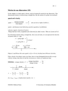
Motion in 1D - Physics
physicscourses.colorado.eduExample: Projectile Motion: A projectile is fired straight up from the ground with an initial speed of |v o | = 10 m/s. Describe the velocity vs. time. (Assume negligible air resistance.) Choose upward as the (+) direction and set the ground at y = 0. y o = …
Related documents
CIRCUITS LABORATORY EXPERIMENT 9 Operational Amplifiers
classes.engineering.wustl.edulinear op amp circuits is to use of negative feedback to always force (V+ - V-) to be suf - ficiently small so that the amplifier is operating in that very narrow linear region. Figure 9.3: Ideal op amp input-output characteristic. There is a simple algorithm for the analysis of an op amp circuit. This algorithm is
Op Amps for Everyone Design Guide (Rev. B)
web.mit.eduthe op amp’s place in the world of analog electronics. Chapter 2 reviews some basic phys-ics and develops the fundamental circuit equations that are used throughout the book. Similar equations have been developed in other books, but the presentation here empha-sizes material required for speedy op amp design. The ideal op amp equations are devel-

Demystifying Type II and Type III Compensators Using Op ...
www.ti.comThe biggest change compared to the conventional Op-Amp approach is the divider network and the OTA g. m. parameter now enters into the equations. Regarding the divider network in the Op-Amp case; thanks to the virtual ground effect, both pins were at a similar potential and the ac contribution of the lower resistor (R. 4) was nonexistent.
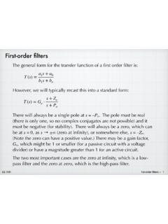
First-order filters - Iowa State University
tuttle.merc.iastate.eduLow-pass filter circuits: non-inverting op amp Note: It might slightly disingenuous to treat this as if it were some new type of filter — we can readily see that it is a simple RC filter cascaded with a simple non-inverting amp. However, it is still a useful circuit. 9 + (V)= =& =&+ =5 = 5& V+ 5& 9R(V)= + 5 5 9 + (V) non-inverting amp ...
Solving circuits directly using Laplace
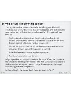
tuttle.merc.iastate.eduequations that arise with circuits that have capacitors and inductors and sources that vary with time (steps and sinusoids.) The approach has been to: 1. Analyze the circuit in the time domain using familiar circuit ... Same op amp circuit, but now with a sinusoidal input. ...
Op Amps for Everyone Design Guide (Rev. B)
web.mit.eduthe op amp’s place in the world of analog electronics. Chapter 2 reviews some basic phys-ics and develops the fundamental circuit equations that are used throughout the book. Similar equations have been developed in other books, but the presentation here empha-sizes material required for speedy op amp design. The ideal op amp equations are devel-

Noise Analysis In Operational Amplifier Circuits (Rev. B
www.ti.comcharacteristic equations that identify noise sources are always integrated over frequency, indicating that spectral density is the natural form for expressing noise ... In op amp circuits, burst noise and avalanche noise are normally not problems, or they can be eliminated if present. They are mentioned here for completeness,

Operational Amplifiers - Concordia College
faculty.cord.eduOperational Amplifier (op-amp) •An op-amp is a high-gain amplifier that has high input impedance and low output impedance. •An ideal op-amp has infinite gain and input impedance and zero output impedance. •An integrated circuit (IC) contains a number of components on a single piece of semiconductor. •Most op-amps are IC chips.
Maxwell’s Equations - Rutgers University
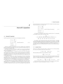
www.ece.rutgers.edu(Maxwell’s equations) (1.1.1) The first is Faraday’s law of induction, the second is Amp`ere’s law as amended by Maxwell to include the displacement current ∂D/∂t, the third and fourth are Gauss’ laws for the electric and magnetic fields. The displacement current term ∂D/∂tin Amp`ere’s law is essential in predicting the
Lecture 7 Circuit analysis via Laplace transform
web.stanford.eduS. Boyd EE102 Lecture 7 Circuit analysis via Laplace transform † analysisofgeneralLRCcircuits † impedanceandadmittancedescriptions † naturalandforcedresponse