
Part B: Design Calculations
1-1 Chapter 1: Introduction Part B of the design report presents a prestressed concrete interior girder as well as the reinforced concrete deck of a 25-meter bridge.
Download Part B: Design Calculations

Information
Domain:
Source:
Link to this page:
Documents from same domain
Part B: Design Calculations - Department of Civil ...
civmin.utoronto.caconducted in Chapter 3 using the concept of influence line to analyze the impact that moving truck loads could bring to the structure. The truck loads are specified differently in each of the Canadian Highway Bridge Design Code S6-14, AASHTO LRFD 2014 Bridge Design Specification, and Design of Highway Bridges S6-66. Therefore, three
Related documents

SLAB ON GRADE REINFORCING DESIGN - PDHonline.com
pdhonline.comWelded Wire Fabric: When using welded wire fabric, prefabricated sheets should be used in lieu of rolled fabric in order to help assure proper location of the steel within the concrete. In either case a minimum of one chair per 25 square feet of mesh should be used to adequately support the reinforcement above the sub-grade. The table provided
315-99 Details and Detailing of Concrete Reinforcement
dl.mycivil.irbars and welded-wire fabric in the structure. The list of bars must show the number of pieces, size, length, mark of bars, and bending details of all bent bars. The list of welded wire fabric must show the mark, style, width, length, and number of pieces. Reinforcing steel for larger structures is …
Masonry Design - Texas A&M University
faculty-legacy.arch.tamu.eduGrades 40 or 50 reinforcement Fs = 20 ksi Grades 60 reinforcement Fs = 32 ksi Wire joint reinforcement Fs = 30 ksi where f’m = specified compressive strength of masonry Internal Equilibrium for Bending Cm = compression in masonry = stress x area = 2 b(kd) fm Ts = tension in steel = stress x area = Asfs STRAIN STRESS Cm = T s and • Mm = T s ...

Section 15 Concrete Reinforcement
www.dot.ny.gov15.4.2 Reinforcement Splicing 15.4.2.1 General Splicing Guidelines For #11 bars or smaller, splices can be made by lap splices with wire ties, mechanical connectors (from the Materials Bureau approved list), or by welding provided it is in accordance with the NYSDOT Steel Construction Manual (SCM), Section 7, Part D. Tack welding is not
Shear Walls •Load Distribution to Shear Walls
efcms.engr.utk.edu1. Maximum spacing of vertical and horizontal reinforcement is min{1/3 length of wall, 1/3 height of wall, 48 in. [24 in. for masonry in other than running bond]}. 2. Minimum area of vertical reinforcement is 1/3 area of shear reinforcement 3. Shear reinforcement anchored around vertical reinforcing with standard hook 4.

INSPECTION GUIDELINES - Miami-Dade County
www.miamidade.govBeam size, reinforcement, splices, reinforcement protection (cover) as per permit plans Tie Beams size reinforcement per plans, but minimum as per. FBC 2121.2.3 Forms and cells free of debris. Horizontal masonry reinforcement as per plans. Request holes if necessary. FBC 2121.1.6 & 2122.2.3 Correct bearing of lintels; check details on permit plans.

IS 2502 (1963): Code of Practice for Bending and Fixing of ...
law.resource.organd bending and fixing procedures for reinforcement, 1.2 The dimensioning and bending of bars specified in this standard applies principally to reinforcement bars conforming to*IS: 432-1960 Specification for Mil(i Steel and Medium Tensile Steel Bars and Hard-Drawn Steel Wire
Concrete Reinforcement Welded Wire Fabric
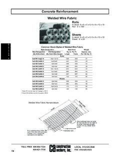
constructionanchors.comCommon Stock Styles of Welded Wire Fabric * Exact W-number size for 8 gauge is W2.1. † Exact W-number size for 2 gauge is W5.4. Concrete Reinforcement Style Designation Steel Area Weight New Designation Old Designation Sq. In. Per Ft. Approx. Lbs. (By W-Number) (By Steel Wire Gauge) Longit. Trans. Per 100 Sq. Ft. Rolls 6x6-W1.4x@1.4 6x6-10x10 ...