
Pipe Flow Expert Example Systems
The example systems supplied with Pipe Flow Expert may be loaded and solved using a trial installation of the software. The example systems are divided into four categories: a. Common Systems – Modelling Specific Items: Pipes, Fittings, Components, Valves and Pumps. b. General Systems – Gravity Flow, Pumped Flow (3 pump types), Energy Recovery.
Download Pipe Flow Expert Example Systems

Information
Domain:
Source:
Link to this page:
Documents from same domain

NPSH - Net Positive Suction Head - Pipe flow
www.pipeflow.comTitle: NPSH - Net Positive Suction Head Author: PipeFlow.co.uk Subject: NPSH / NPSHa - Net Positive Suction Head Keywords: NPSH NPSHa Net Positive Suction Head

Darcy-Weisbach Formula - Pipe Flow Software
www.pipeflow.comTitle: Darcy-Weisbach Formula Author: PipeFlow.co.uk Subject: Darcy-Weisbach Equation / Formula Keywords: Darcy-Weisbach Darcy Weisbach Friction Loss

Viscosity and Density Units and Formula - Pipe Flow
www.pipeflow.comDensity p The density of a fluid is obtained by dividing the mass of the fluid by the volume of the fluid. Density is normally expressed as kg per cubic meter. p = kg/m3 Water at a temperature of 20°C has a density of 998 kg/m3 Sometimes the term ‘Relative Density’ is used to describe the density of a fluid.

Laminar and Turbulent Flow in Pipes - Pipe Flow
www.pipeflow.comPipes with less smooth walls such as concrete, cast iron and steel will create larger eddy currents which will sometimes have a significant effect on the frictional resistance. The velocity profile in a pipe will show that the fluid at the centre of the stream will move
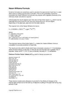
Hazen Williams Formula - Pipe Flow
www.pipeflow.comHazen-Williams Formula Empirical formulae are sometimes used to calculate the approximate head loss in a pipe when water is flowing and the flow is turbulent. Prior to the availability of personal computers the Hazen-Williams formula was very popular with engineers because of the relatively simple calculations required.
Related documents

HVAC DUCT CONSTRUCTION STANDARDS
webstore.ansi.orgHVAC Duct Construction Standards Metal and Flexible ... rication and installation of duct systems. Suggestions for future improvement are welcome. Special thanks is given ... the contents of this document or publication and it has no role in any representations by other parties that specific components are, in fact, in compliance with it. 3 ...
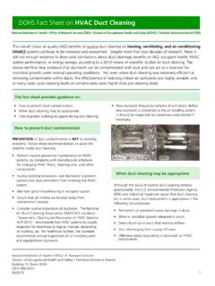
DOHS Fact Sheet On HVAC Duct Cleaning
ors.od.nih.gov• Perform routine preventive maintenance on HVAC systems, by complying with manufacturer schedules for changing HVAC filters, cleaning coils, and other components. • During building renovation, seal ductwork to prevent construction dust and debris from entering the HVAC system. • Maintain good housekeeping in occupied spaces.

08 - Mini-split AC systems, heat pumps, VRV multi-zone ...
www.daikinac.comDaikin is an industry-leading HVAC technology company. ... Daikin VRV systems provide advanced solutions for almost any large residential to commercial application. Available in air-cooled or water-cooled solutions and heat recovery or heat ... for additional components
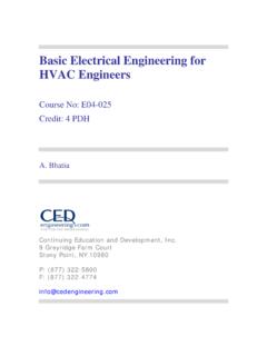
Basic Electrical Engineering for HVAC Engineers
www.cedengineering.comown merits and demerits, but for an HVAC system or typical building services, we are concerned with AC voltage. Industrial AC voltage levels are roughly defined as LV (low voltage) and HV (high voltage) with frequency of 50 to 60 Hz. An electrical circuit has the following three basic components irrespective of its electrical energy form: 1.

Design Options for HVAC Distribution Systems
www.cedengineering.comcomponents serve as an interface between the distribution system and occupied spaces. In this course we will focus on the various design options pertaining to cooling and heating air distribution (item numbers 3 and 4 above). HVAC systems are of great importance to architectural design efforts for three main reasons. 1. These systems consume ...

Getting Started with Niagara 4
lghvac.comGetting Started with Niagara . Due to our policy of continuous product innovation, some specifications may change without notification. 5

HVAC COMPONENTS AND SYSTEMS - okohausger.com
www.okohausger.comThe HVAC Components and Systems module of the Vital Signs Project was developed at the School of Architecture, Florida A & M University (FAMU), Tallahassee, FL. The assistance of the Institute for Building Sciences, School of Architecture, and Division of Sponsored Research at Florida A & M is acknowledged.
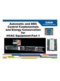
Automatic and DDC Control Fundamentals and Energy ...
buildingretuning.pnnl.govHVAC Control Principles 1. Intent of Battelle Pacific NW Division involvement 2. Purpose of Controls 3. Keyyp y Components of Control Systems 4. Control Loops, Open vs. Closed Loops 5. Terminology 6. The Control Cycle and Control Actions 7. Th E S f C t l S tThe Energy Sources for Control Systems 8. DDC Point Types PNWD-SA-8834 1-4