
Protective Equipotential Bonding
in electrical installations, the most commonly used ... measure in which basic protection is provided by basic insulation of live parts or by barriers or enclosures and fault protection is ... case of a fault. Main protective equipotential bonding The purpose of earthing the exposed-conductive-parts of an installation is to ensure that, in the ...
Download Protective Equipotential Bonding

Information
Domain:
Source:
Link to this page:
Documents from same domain

Corrigendum Requirements for Electrical …
electrical.theiet.orgRequirements for Electrical Installations IET Wiring Regulations, Seventeenth Edition. Corrigendum (January 2016) This Corrigendum contains corrections to BS 7671 ...
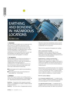
EARTHING ANDBONDING IN HAZARDOUS LOCATIONS
electrical.theiet.orgHAZADOUS LOCATIONS. IEE Wiring Matters | Spring 2006 | www.iee.org. 17. Equipotential bonding connections. BS EN 60079-0:2004, Electrical apparatus for explosive

Requirements for Electrical Installations READ N RERDTINR
electrical.theiet.orgInstallations, IET Wiring Regulations 18th Edition and its updating with the first amendment, published in 2020. BS 7671 and the IET/IEE Wiring Regulations have been extensively referred to in HSE guidance over the years. Installations which conform to the standards laid down in BS 7671:2018+A1:2020 are regarded by HSE as likely

Electrical Installations ONLY READ REPRODUCTIONFOR NOT
electrical.theiet.orgPublication Information Published by the Institution of Engineering and Technology, London, United Kingdom in agreement with BSI. The Institution of Engineering and Technology is registered as a Charity in England & Wales (no. 211014) and

Requirements for Electrical Installations
electrical.theiet.org514.12 Notices: periodic inspection and testing ... a report on its condition obtained, as prescribed in the IET ... Electrical equipment shall be selected and erected so as to avoid any harmful influence between the electrical installation and any …

Model Forms Minor Electrical Installation Works Certificate
electrical.theiet.org(vii) An Electrical Installation Condition Report will indicate the responsibility for the inspection and testing of an existing installation within the extent and limitations specified on the report. (viii) Schedules of inspection and schedules of test results as required by Part 6 should be issued with the associated

ELECTRICAL INSTALLATIONS OUTDOORS: ASUPPLYTO A …
electrical.theiet.orgshould be fitted with circuit-breakers for the two final circuits such as 6A for the lighting circuit and 16A for the socket-outlet circuit. The socket-outlet is very likely to be used to supply portable equipment outdoors and RCD protection must be provided by an RCD with a rated residual operating current not exceeding 30mA.

Power Factor Correction - BS 7671 Home of the Wiring ...
electrical.theiet.orgA load with a power factor of, say, 0.8, results in much higher losses in the supply system and a higher bill for the consumer. A comparatively small improvement in power factor can bring about a significant reduction in losses since losses are proportional to the square of the current. When the power factor is less than one the ‘missing’

Requirements for Electrical Installations
electrical.theiet.orgAny symbol used shall comply with IEC 60617. 514.10 : Warning notice: voltage 514.10.1: Every item of equipment or enclosure within which a nominal voltage exceeding 230 volts to earth exists and where the presence of such a voltage would not …

Model Forms Electrical Installation Condition Report
electrical.theiet.orgElectrical Installation Certificate or Electrical Installation Condition Report. ... 6 Where an installation has an alternative source of supply a further schedule of supply characteristics and earthing arrangements based upon Section I of this Report should be provided. 7 A summary of the condition of the installation in terms of safety should ...
Related documents
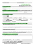
Original Certificate Certificate reference: ELECTRICAL ...
www.electricaltestcertificates.co.uk4.1 Double insulation 4.2 Reinforced insulation 4.3 Use of obstacles 4.4 Placing out of reach 4.5 Non-conducting location 4.6 Earth-free local equipotential bonding 4.7 Electrical separation for more than one item of equipment 5. 0 Distribution equipment 5.1 Adequacy of working space/accessibility of equipment 5.2 Security of fixing
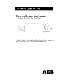
Technical Guide No. 102 - ABB
library.e.abb.comThe various electrical conductors that form the motor stator windings must be electrically insulated from each other and from the metal parts of the motor struc-ture. Insulation is required wherever there is a difference of electrical potential between two (2) conductors. Turn-to …

ELECTRICAL INSTALLATION CERTIFICATE
www.electricaltestcertificates.co.ukReport reference: ELECTRICAL INSTALLATION - GREEN.odt Report pages including inspection and test schedules 1 of 7 ... Bonding of extraneous conductive parts ... insulation used PELV Segregation of safety circuits Basic protection Identification Insulation of live parts Presence of diagrams, instructions, circuit charts and

Guide to Electrical Safety Testing - Hipot
go.hipot.comconductive material such as plastic or wood. This ensures no stray leakage current could flow through you during a test. DUT Safety Enclosure Signal Tower Light Non-Conductive Work Bench A E H Tester used to test the DUT. Electrical Safety Tester B Test Operator C High Voltage Insulation Mat This isolates you from ground which

Insulation Resistance Testing - Southwire
media.industrial.southwire.comInsulation Resistance Testing Purpose: Insulation resistance testing is a non-destructive test procedure. The test measures the insu-lation resistance between the phases and/or between phase and ground. It is commonly used in the industry for acceptance testing prior to energizing the cable and for maintenance testing programs.

3M Electrically Conductive Adhesive Transfer Tape 9703
multimedia.3m.comElectrical Properties: Insulation Resistance2,3 3.4 x 10¹⁴ ohms/square (estimated based on 3M™ Electrically Conductive Adhesive Transfer Tape 9703) Contact Resistance1 < 0.3 ohms (3M Test Method, Gold PI Flex onto Gold PCB, RT Initial R, 6 mm2) Minimum Gap4 15 mil (0.4 mm) Minimum Overlap Area5 5000 mil2 (3.2 mm2)

IEC 60364-6: Low voltage electrical installations – Part 6 ...
www.emo.org.trElectrical installation safety ... insulation resistance; c) insulation resistance testing to confirm the effectiveness of protection by SELV ... The continuity of conductors and connection to exposed-conductive-parts, if any, shall be verified by a measurement of resistance on protective conductors, including protective bonding conductors ...

Electrical Safety Outline
www.ewh.ieee.org• BS 5724: Electrical Safety of Medical Equipment. 16 Classification of Medical Equipment • Class I[ No Symbol]:- equipment in which protection against electric shock does not rely solely on basic insulation but also provided by connecting all accessible conductive parts to the protective earth conductor of the mains wiring. So, these parts

IEC 60664-1 ED3 Insulation coordination
www.ieee802.orgSolid insulation of basic insulation, supplementary insulation and reinforced insulation shall be capable of durably withstanding electrical and mechanical stresses as well as thermal and environmental influences which may occur during the intended life of the equipment.
Electrical Safety Testing Reference Guide
www.psma.comFeb 28, 2001 · An insulation resistance testmeasures the quality of the electrical insulation used in a product. A leakage current testchecks that the current that flows between AC source and ground does not exceed a safe limit. A ground continuity testchecks that a path exists between all exposed conductive metal surfaces and the power system ground.