SPLINES AND SERRATIONS - Autodesk
2128 INVOLUTE SPLINES Diametral Pitch (P) is the number of spline teeth per inch of pitch diameter.The diame-tral pitch determines the circular pitch and the basic space width or tooth thickness. In con-junction with the number of teeth, it also determines the pitch diameter.
Download SPLINES AND SERRATIONS - Autodesk

Information
Domain:
Source:
Link to this page:
Documents from same domain

SOUTH AFRICAN NATIONAL STANDARD - Autodesk
forums.autodesk.comThis South African standard was approved by National Committee SABS SC 59F, Construction standards – Steel and aluminium structures, in accordance with procedures of the SABS Standards Division, in compliance with annex 3 of the WTO/TBT agreement.

Process Industry Practices Piping - Autodesk …
forums.autodesk.comand particular matters or application of the Practice to particular project or ... Process Industry Practices . Piping . ... of each PIP Material Specification.

Table 1. Limits on Crest and Root of American …
forums.autodesk.comAMERICAN PIPE THREADS 1849 Table 4. Basic Dimensions, American National Standard Taper Pipe Threads, NPT ANSI/ASME B1.20.1-1983 (R1992) For all dimensions, see corresponding reference letter in table.

AutoCAD 2015 PRODUCT FOCUS - Autodesk Community
forums.autodesk.com18 www.augi.com September 2014 AutoCAD 2015 PRODUCT FOCUS LINKING A SCALE BAR TO A VIEWPORTHow many times have you opened a drawing file and looked at the scale and it was not the same as the viewport? Let’s take fields one step further and link to a viewport, adding a formula to modify
Rev-Leverging 2D data in 3D Modeling - Autodesk
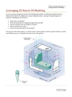
forums.autodesk.comLeveraging 2D Data in 3D Modeling ... The utility essentially takes a single imported 2D drawing that was placed into a sketch and builds the required work planes and sketches in order to accommodate ...

Autodesk Building Systems & DIALux Link
forums.autodesk.comAccording the the DIALux website, the DIALux lighting design tool is being used by more and more lighting designers worldwide and an increasing number of reputable lighting manufacturers worldwide use this platform to present their data.

Converting Acad Files to Other Formats Using Visio
forums.autodesk.comConverting Acad Files to Other Formats Using Visio: (For use with AutoCAD® / Autodesk® software & Microsoft Visio): Once the file is open in Visio, simply save as a SVG file. ... ¾ STL – (Lithography) “This is the MAIN format used to export files in a usable 3D format” (*2).

Diagrams, Device Designations, and Symbols for Industrial ...
forums.autodesk.comNEMA disclaims liability for any personal injury, property, or other damages of any nature whatsoever, whether special, indirect, consequential, or compensatory, directly or indirectly ... responsibility of the certifier or maker of the statement. ICS 19-2002 (R2007) Page i

Drawing, Drafting, & Modeling Standards and Practices ...
forums.autodesk.comMay 13, 2010 · document 10-0005, Blah Drawing & Drafting Standards and Practices , for the proper setup of a sheet metal drawing. For door panels, front panels, interior panels, and racks see document 10-1006 for information on adding a note regarding the implementation EPS-121.

AutoCAD Electrical Symbol Libraries - Autodesk
forums.autodesk.comConfiguration and Ladder Master Line Reference Symbols AutoCAD Electrical expects to find these block inserts: WD_M.dwg block insert consisting of about 50 invisible attributes. These carry the drawing’s settings. WD_PNLM. dwg optional block insert consisting of several invisible attributes. These carry the drawing’s settings for panel
Related documents

IS 3665 (1966): Dimensions for involute sided splines
law.resource.orgsplines have already been prepared (see IS : 2327-1963* and IS : 2610- I96W )* 05 The dimensions and fits given in the tables are based on the basic hole system. In this system the dimensions of the internal splines are the basis and variations in fit are obtained by varying the allowance on the external ...

Cubic Splines - Stanford University
aero-comlab.stanford.eduTo study convergence properties of splines we need an estimate of the norm of the inverse of the matrix Bof the equations for the spline. Taking kxk= maxjx ij the induced norm of Bis kBk= sup x6=0 kBxk kxk = max i Xn j=1 jb ijj 9. With a diagonally dominant matrix we have kyk= kBxk = max i Xn j=1 b ijx j Xn j=1 b ijx j where kxk= jx kj, or kyk ...

Splines - Sharif
mech.sharif.irSplines Mott, Fig. 11-6 Splines can be thought of as a series of axial keyways with mating keys machined onto a shaft. There are two major types of splines used in industry: 1) straight-sided splines, and 2) involute splines. Splines provide a more uniform circumferential transfer of torque to the shaft than a key.

Dreamteck Splines – User Manual
dreamteck.ioDreamteck Splines – User Manual 8 1. Getting Started Dreamteck Splines is a Spline system and extension for Unity which comes with a collection of tools and

Bezier Curves and Splines - MIT OpenCourseWare
ocw.mit.eduSplines . 16 . 6.837 – Durand . Tessellation • It is easy to rasterize mathematical line segments into pixels –OpenGL and the graphics hardware can do it for you • But polynomials and other parametric functions are harder . Image courtesy of Phrood on Wikimedia Commons. License: CC-BY-SA.This content is excluded from our

Spline Curves - Clemson University
people.cs.clemson.eduChapter 14 Spline Curves A spline curve is a mathematical representation for which it is easy to build an interface that will allow a user to design and control the ...

B-Splines and NURBS - Drexel CCI
www.cs.drexel.edu–uniformB-splines –Curve does not interpolate end points •first blending function not equal to 1 at t=0 •Uneven distribution of knots –non-uniformB-splines –Allows us to tie down the endpoints by repeating knot values (in Cox-deBoor, 0/0=0!) –If a knot value is …
Design Parameters for Spline Connections
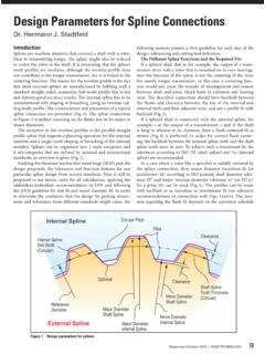
www.geartechnology.comIf the splines are being designed, then one of the preferred pres-sure angles from the standards should be used. ANSI and DIN offer the choice between 30°, 37.5° and 45°. In the JIS standard also a pressure angle of 20° is proposed. If the spline is designed for an aftermarket product (for example the sprocket shown Fig. 7), then a simple ...

Linear Interpolating Splines - USM
www.math.usm.eduLinear Interpolating Splines We have seen that high-degree polynomial interpolation can be problematic. However, if the tting function is only required to have a few continuous derivatives, then one can construct a piecewise polynomial to t the data. We now precisely de ne what we mean by a piecewise polynomial.