
Structural Stability and Determinacy
5 Axial Force, Shear Force and Bending Moment Diagram of Multi-Storied Frames Example 2.2 Draw the axial force, shear force and bending moment diagrams of the three-storied frame loaded as shown
Download Structural Stability and Determinacy

Information
Domain:
Source:
Link to this page:
Documents from same domain

Design of Balanced Cantilever Bridge
www.uap-bd.edu1. Design of Slab Bridge width = 30 , Number of girders = 6@15 Clear span between girders S = (30 – 6 15 )/5 = 4.5 The c/c distance between girders = 4.5 + 15 = 5.75

Fourier Optics and Computer Generated Hologram
www.uap-bd.eduFourier Optics and Computer Generated Hologram 3 Computer Generated Holography is an optical numerical technique, which avoid the traditional light interference recording process by computer numerical calculation
Approximate Lateral Load Analysis by Portal Method
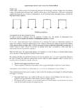
www.uap-bd.edu1 Approximate Lateral Load Analysis by Portal Method Portal Frame Portal frames, used in several Civil Engineering structures like …

Iso” means „equal‟ and “metric projection” means „a ...
www.uap-bd.edu5 BOX METHOD: The isometric projection of solids like cube, square and rectangular prisms are drawn directly when their edges are parallel to the three isometric axes.
DEVELOPMENT OF SURFACES
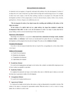
www.uap-bd.edu2 DEVELOPMENT OF SECTIONS Develop the surfaces of the cube of 1" Develop the surfaces of a triangular prism Develop the surfaces of a pyramid B
Torque Diagram and Torsional Stress of Circular …
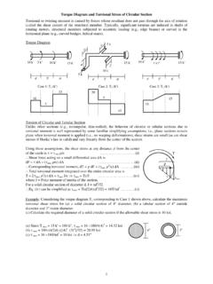
www.uap-bd.edu1 Torque Diagram and Torsional Stress of Circular Section Torsional or twisting moment is caused by forces whose resultant does not pass through the axis of rotation
One-way and Two-way Slabs - University of Asia …
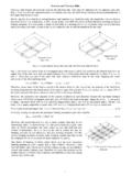
www.uap-bd.edu4 Design of Two-way Slabs Example 1.2 Use (i) WSD, (ii) USD to design the two-way slab shown below, carrying floor finish = 30 psf, random wall = 50 psf

Design of Industrial Truss - University of Asia Pacific
www.uap-bd.edu3. Load Combination and Design of Truss Members The member forces and support reactions calculated earlier for point dead loads and wind loads

Joint Displacements and Forces - University of Asia …
www.uap-bd.edu5 Boundary Conditions, Support Reactions and Member Forces After assembly of the member stiffness matrices, the equilibrium equations were 1.5 0.5 1 0 0 0 0.5 0.5

Diagrammatic Convention for Supports - …
www.uap-bd.edu3 Integration Method for SFD and BMD Example 1.2 Derive equations for the shear force and bending moment of the beams loaded as shown below. Also …
Related documents
Gusset Plate Stress 7a - ARC Structural
arcstructural.comConnection Design for Steel Structures Chapter 7a, Page 1 of 21 Copyright © 2011 by Bo Dowswell
STRENGTH OF MATERIALS-I
gvpce.ac.inG V P College of Engineering (Autonomous) 2013 STRENGTH OF MATERIALS-I Course Code : 13CE1106 L T P C 410 3 Course Educational Objectives: To create a strong understanding about the behaviour of engineering materials under deformable bodies under the action of various types
MECHANICAL ENGINEERING UNIT 1: …
trb.tn.nic.inMECHANICAL ENGINEERING UNIT 1: ENGINEERING MATHEMATICS Linear Algebra: Matrix algebra, Systems of linear equations, Eigen values and eigen vectors. Calculus: Functions of single variable, Limit, continuity and differentiability, Mean value theorems, Evaluation of definite and improper integrals, Partial derivatives,

Lect10 - Columns Interaction Diagrams
www.avant-garde-engineering.comtÜ~í=fë=qÜÉ=bÑÑÉÅí=lÑ= `çäìãå=päÉåÇÉêåÉëë\ Imagine the effect of purely axial load applied in this element. What do you think will happen? Even if there is no shear or moment applied, do you believe that it will crush from the axial load? The uniformity and homogeneity of the material should be challenged.

Shear and Moment Diagrams for Frames - Civil …
www.ce.memphis.eduShear and Moment Diagrams for Frames A frame is a structure composed of several members that are either fixed– or pin–connected at their ends. It is often necessary to draw shear and moment
Approximate Lateral Load Analysis by Portal Method
www.uap-bd.edu2 Example Draw the axial force, shear force and bending moment diagrams of the frames loaded as shown below. E D (i) (ii)

v2.0 User manual - engissol.com
www.engissol.comPROGRAM FEATURES The Frame Analysis application is available in 3 different packages (Static, Dynamic and Truss). Static Analysis version: Static analysis of all kind of frames Truss analysis version: Static analysis of all kind of trusses Dynamic analysis version: Static and dynamic analysis of all kind of frames and trusses Each licensed …