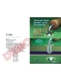
Through Hole Solder Joint Evaluation
Through Hole solder joint evaluation, and therefore, it references portions of the fol-lowing IPC standard: The IPC-A-610 Rev. F, Acceptability of Electronic Assemblies, which illustrates the requirements for many types of solder connections. Classification Through Hole solder joint requirements are divided into three classes depending
Download Through Hole Solder Joint Evaluation

Information
Domain:
Source:
Link to this page:
Documents from same domain
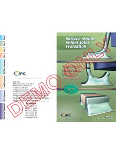
Photos Class 3 Class 2 Class 1 J-Lead Components
www.ipctraining.orgArea Array Components Chip Components Class 1 Class 2 J-Lead Components Gull Wing Components Class 3 Photos 1 TABLE OF CONTENTS Introduction2 Acceptance Criteria 2

This Promotional Sample - IPC
www.ipctraining.org2 Introduction toElectronics Assembly Electronics Assembly 3 Introduction Look around. Electronic prod-ucts are everywhere. They’re in our homes, offices, schools, ...

Minimum Through-Hole Solder Joint Requirements …
www.ipctraining.orgReferences: IPC-A-610E and IPC J-STD-001E © IPC 2010, 3000 Lakeside Drive, Suite 309-S Bannockburn, IL 60015-1249 Tel. 847.615.7100 • FAX: 847.509.9798 www.ipctraining.org • e-mail: orderipc@ipc.org
P-PTH 2-F v2 demo - IPC
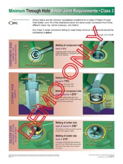
www.ipctraining.orgMinimum Through Hole Land Shown below are the minimum acceptable conditions for a Class 3 Plated-Through Hole Solder Joint. All of the illustrations show the same solder connection from three
DEMO ONLY Version - IPC
www.ipctraining.orgChip Components Class 1 Class 2 J-Lead Components Gull Wing Components Class 3 Photos 1 TABLE OF CONTENTS Introduction2 Acceptance Criteria 2 Lead Free 2
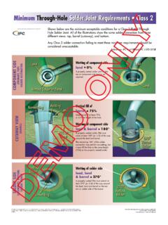
Minimum Through-Hole Solder Joint …
www.ipctraining.orgReferences: IPC-A-610E and IPC J-STD-001E © IPC 2010, 3000 Lakeside Drive, Suite 309-S Bannockburn, IL 60015-1249 Tel. 847.615.7100 • FAX: 847.509.9798 www.ipctraining.org • e-mail: orderipc@ipc.org
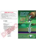
Guide — DRM-PTH-E. Evaluation - IPC
www.ipctraining.orgThrough-Hole Solder Joint Evaluation Training and Reference Guide 6 Acceptance Criteria In this Training and Reference Guide, criteria are given for each class in one or
ESD CONTROL FOR ELECTRONICS ASSEMBLY TRAINING ...
www.ipctraining.orgESD CONTROL FOR ELECTRONICS ASSEMBLY TRAINING CERTIFICATION TEST (DVD-74C) v.2 3 1. Most people feel ESD above a. 2,000 volts b. 20,000 volts c. 20 volts
ESD CONTROL FOR MATERIAL HANDLERS TRAINING …
www.ipctraining.orgESD CONTROL FOR MATERIAL HANDLERS TRAINING CERTIFICATION TEST (DVD-77C) v.3 1 This test consists of twenty multiple-choice / true-false questions.
HANDLING MOISTURE SENSITIVE DEVICES …
www.ipctraining.orgHANDLING MOISTURE SENSITIVE DEVICES TRAINING CERTIFICATION TEST (DVD-79C) v.3 1 This test consists of twenty multiple-choice questions. All questions …
Related documents

Miniature Signal Relays EC2/EE2
content.kemet.com• Surface mount and through-hole options • High Breakdown Voltage (NKX) type can withstand 1.5 kVAC at open contacts Overview The KEMET EC2/EE2 miniature signal relays offer a ... EE2-3(1)NUX-L 3.0 Surface mount, High solder joint reliability Tape on Reel EE2-4.5(1)NUX-L 4.5 Surface mount, High solder joint reliability Tape on Reel ...
SMT Board Assembly Process Guide - Intel
www.intel.comHere is a method for placing TC’s to measure SMT joint temperatures: Before the component is soldered to the board, drill a small hole through the pad of the joint to be measured Insert the thermocouple from the bottom of the board Hold the thermocouple tip flush with the top surface of the board

Recommended Soldering Techniques
www.diodes.com: Solder may not adhere to the leads or terminals of a device if the plating thickness is too thin. This problem especially applies to axial-leaded devices since the solder must bridge across the through-hole from the pad to the lead (Figure 8). 2.
Guidelines for Design, Selection and Application of ...
www.ipc.orgIPC-HDBK-830A Guidelines for Design, Selection and Application of Conformal Coatings Developed by the Conformal Coating Handbook Task Group (5-33c) of

Tow-Pro Wiring Kit - Ford Ranger / Everest
www.redarc.com.auSolder the wires to the Butt Splice. Ensure that a good connection is made. Wait for the Butt Splice to cool, slip the Heatshrink over the joint and heat. Reconnect the 16-way connector (1). Keep heatshrink away from joint until after soldering is complete and cooled. Proceed to Step 30. Page 13 of 3 12 34

MSL Ratings and Reflow Profiles (Rev. A) - TI.com
www.ti.comsolder paste is starting its activity and cleaning process of all surfaces involved into the later solder joint begins. • Liquidous temperature (TL) for lead-free soldering - this is approximately 217°C. ... Wave soldering is an older technology that is frequently used for soldering through-hole components or the larger pitch packages, such ...

Metal Film Resistors, Axial, Military/Established ...
www.vishay.com(3) Hot solder dipped leads. (4) Tolerance of ± 0.1 % is not applicable to characteristics K. STANDARD ELECTRICAL SPECIFICATIONS GLOBAL MODEL MIL-PRF-55182 STYLE MIL SPEC. SHEET POWER RATING P70 °C W POWER RATING P125 °C W TOLERANCE (4) ± % MAXIMUM WORKING VOLTAGE (2) V RESISTANCE RANGE Ω TEMPERATURE …