
TR-35 Upper Board Assembly Instructions
procedure as for D8. The longer lead goes to the square hole. Solder and trim 2 leads. 7) Install and solder D8, the red low battery warning LED, using the same procedure as for D6 and D7 above. The longer lead goes to the square hole. Solder and trim 2 leads. 8) Install and solder electrolytic capacitors C3 and C13, 100uF, tight against the board.
Download TR-35 Upper Board Assembly Instructions

Information
Domain:
Source:
Link to this page:
Related documents
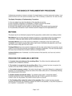
THE BASICS OF PARLIAMENTARY PROCEDURE
octsa.ua.eduParliamentary procedure is simple in principle. It is based largely on common sense and courtesy. It just seems technical due to the special vocabulary used. If the vocabulary is understood, the rules are easy. The Basic Principles of Parliamentary Procedure: 1. Only one subject may claim the attention of the assembly at one time. 2.
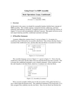
Going From C to MIPS Assembly Basic Operations: Loops ...
courses.cs.washington.eduFigure 4.2: Assembly versions of strlen This is a remarkably simple procedure, but it gives a good illustration of the loop construct in action. In this case, we are using a simple counting loop that terminates as soon as the character we are looking …

3000 Series Owner's Manual - Dell
downloads.dell.comInspiron 15 3000 Series Owner's Manual Computer Model: Inspiron 15–3541/15–3542 Regulatory Model: P40F Regulatory Type: P40F001/P40F002

Safe Operating Procedure
ehs.unl.eduo If a platform or elevating assembly becomes caught, snagged, or otherwise prevented from normal motion by adjacent structures or other obstacles such that control reversal does not free the platform, all personnel must be removed from ... Safe Operating Procedure ...

Quick install guide - images.thdstatic.com
images.thdstatic.comprocedure MUST be performed before any electrical power is turned on. Electrical Connection Check all wires to make sure they are securely fasten and tight. Before turning the power ON make sure the system has been flushed as required in the plumbing section. When the unit is powered up turn the control knob to turn ON the GREEN LED indicator

Rules Procedure - International Criminal Court
www.icc-cpi.intThe Rules of Procedure and Evidence of the International Criminal Court do not affect the procedural rules for any national court or legal system for the purpose of national proceedings. ** The Rules of Procedure and Evidence are reproduced from the Official Records of the Assembly of States Parties to the Rome Statute of the International