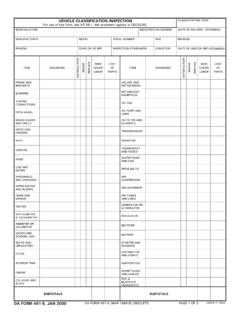
VEHICLE CLASSIFICATION INSPECTION - Army.com
piston rings int and exh manifolds oil pan oil pump and lines oil filter and elements transmission radiator thermostat and hoses water pump and fan drive belts air compressor air governor ... hoist or crane svc brake system master cylinder air hydraulic cylinder wheel cylinders hand brake system steering gear and controls springs and shackles shock
Download VEHICLE CLASSIFICATION INSPECTION - Army.com

Information
Domain:
Source:
Link to this page:
Documents from same domain
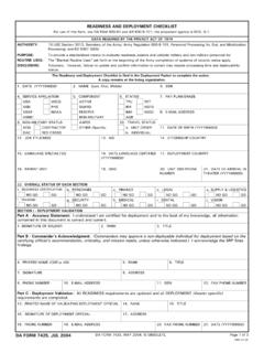
READINESS AND DEPLOYMENT CHECKLIST - …
www.armyreal.comDA FORM 7425, MAY 2004, IS OBSOLETE. 5. COMPONENT 9. NON-MILITARY STATUS READINESS AND DEPLOYMENT CHECKLIST For use of this form, see DA PAM 600-81 and AR 600-8-101; the proponent agency is DCS, G-1.
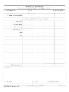
STRENGTH AND FEEDER REPORT - armyreal.com
www.armyreal.comSTRENGTH AND FEEDER REPORT For use of this form, see DA PAM 30-22; the proponent agency is DCS, G4. 3. DATE (YYYYMMDD) 6. MEALS SOLD FOR CASH 8a. SIGNATURE
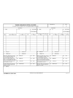
TRAINING AMMUNITION CONTROL DOCUMENT 1. …
www.armyreal.com25. date turned in 32. turned-in by 14. issued by 15. received by 8. dodic/nomenclature 7. item 26. qty. training ammunition control document

INTERVIEW PLAN #2 STRUCTURED INTERVIEW …
www.armyreal.cominterview plan #2 structured interview army precommissioning selection college background and/or military service for official use only - only when filled out

BASE SYSTEM CIVILIAN EVALUATION REPORT - …
www.armyreal.coma. NAME OF RATER (Last, First, Middle Initial) d. ORGANIZATION/INSTALLATION BASE SYSTEM CIVILIAN EVALUATION REPORT For use of this form, see AR 690-400; the proponent agency is ASA(M&RA)
INSTRUCTIONS FOR COMPLETING DA FORM 7425, …
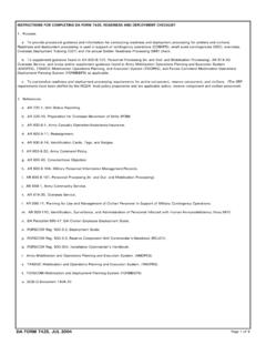
www.armyreal.comINSTRUCTIONS FOR COMPLETING DA FORM 7425, READINESS AND DEPLOYMENT CHECKLIST 1. Purpose. a. To provide procedural guidance and information for conducting readiness and deployment processing for soldiers and civi lians.

UM ITEM NOUN UI - armyreal.com
www.armyreal.comTitle: DA Form 1300-4, JAN 82 Author: APD Subject: REORDER POINT RECORD Keywords: REORDER POINT RECORD Created Date: 10/6/2005 6:06:55 PM
CHECKLIST AND TRACKING DOCUMENT FOR …
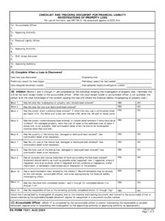
www.armyreal.como Compiled evidence substantiating or refuting any statement in block 9, DD Form 200. Has the accountable officer completed blocks 17a through 17f showing the
10-METER BORESIGHT OFFSET TARGET - …
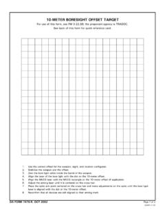
www.armyreal.com10-METER BORESIGHT OFFSET TARGET For use of this form, see FM 3-22.68; the proponent agency is TRADOC. See back of this form for quick reference card.

RECORD OF PROCEEDINGS UNDER ARTICLE 15, …
www.armyreal.comRECORD OF PROCEEDINGS UNDER ARTICLE 15, UCMJ For use of this form, see AR 27-10; the proponent agency is TJAG. 10
Related documents
GM Inline Engines - West Virginia University
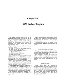
web.statler.wvu.edu4. Remove the piston rings. It is not necessary to separate the pistons from the connecting rods unless a piston, connecting rod or piston pin needs repair or replacement. 5. Assemble by reversing Steps 1-4. General Overhaul 1. Remove the engine from the boat. 2. Remove the flywheel. 3. Remove the engine mount brackets and oil

Ordinary Lift Planning and Control Form - Stanford University
www-group.slac.stanford.eduShow location of shackles, hoist rings, spreader beams, slings, etc . 2. Show attachment points (how rigging gear will be attached to load) 3. Show where padding of sharp edges are necessary 4. Provide the weight of heavy equipment such as a lifter or spreader beam, or fork beam (forklift attachment) 5. Show proper orientation of eyebolts

DISASSEMBLY & REASSEMBLY INSTRUCTIONS - Muncie …
www.munciepower.comHoist Hydraulic Press (To hold cylinder to table) Wiper, Typically Grey but may be Blue, Has "Deep" Groove TOOLS USED Below are the tools commonly used to disassemble and reassemble a Muncie ... Rings. 12 DISASSEMBLY 13. Remove the snap rest ring by means of a straight blade screw driver. Use extreme caution as

OVERHEAD CRANE PRE-OPERATIONAL CHECKLIST - …
www.oshatrain.org- Each Hoist/Load Block - Motor Coupling * Trolley Drive - Gear Reducer - Wheels, Driver * - Gear Reducer Oil Seals - Wheels, Idler * - Axle Pinion - Wheels Bearings * - Axle Gear ... - Bridge Motor Rings - Bridge Contactors - Trolley Motor Bearings - M.H. Overhead Relays

INDUSTRIAL JIB CRANES - Spanco
www.spanco.comCollector Rings or Air Swivel for Continuous Rotations Full Cantilever : or Drop Cantilever Models Full : Cantilever or Tie-Rod Models Freestanding, Ceiling-Mounted, or Wall-Mounted Freestanding, Portable Base, or : Wall-Mounted ... Also factor in the size of the hoist and the

ZF 6HP26 / 6HP28 - The CTSC
www.thectsc.comSelective Shims, Snap Rings, Steel Plate & Kits Content Each transmission is divide into groups (e.g. gearbox housing group). The position number (Position #) is used to identify the location of each spare part in the transmission. A position number like 01.010 is either a

80 - Weil-McLain
www.weil-mclain.com4. Place 7½” and 3½” sealing rings in appropriate port openings. See Figure 4. If sealing ring slips out of groove, stretch ring gently for several seconds, then reposition in groove. 5. Apply continuous bead of silicone sealant no larger 1/ 16 ” around entire outside edge of outer machined surface of port. Refer to Figure 5. Do not apply