Verilog Tutorial - UMD
Verilog is a HARDWARE DESCRIPTION LANGUAGE (HDL). A hardware description Language is a language used to describe a digital system, for example, a network switch, a microprocessor or a memory or a simple flip−flop. This just means that, by using a HDL one can describe any hardware (digital ) at any level. 1// D flip−flop Code
Download Verilog Tutorial - UMD

Information
Domain:
Source:
Link to this page:
Documents from same domain
Exception and Interrupt Handling in ARM
classweb.ece.umd.eduException and interrupt handling is a critical issue since it affect directly the speed of the system and how fast does the system respond to external events and how does it deal with more than one external event at the same time by assigning priorities to these events.
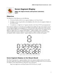
Seven-Segment Display - UMD
classweb.ece.umd.eduA 7-segment display contains seven light emitting diodes (LEDs) Seven-Segment Displays on the Nexys2 Board!e Nexys2 board has four 7-segment displays. Each seven-segment display consists of seven LED bars and a single LED round (for the decimal point), as shown in the figure below. You can reference
Plasma Enhanced Chemical Vapor Deposition (PECVD)
classweb.ece.umd.eduChemical Vapor Deposition for Microelectronics Principles, Technology, and Applications. Park Ridge, NJ: Noyes Publications, 1987. QUESTIONS? Title: Microsoft PowerPoint - PECVD Presentation.ppt Author: nganig Created Date: 10/24/2007 2:14:06 PM ...
Damascene Process and Chemical Mechanical Planarization
classweb.ece.umd.eduOct 17, 2011 · Damascene Process Steps Damascene is an additive process Firstly, the dielectric is deposited Secondly, the dielectric is etched according to the defined photoresist pattern, and then barrier layer is deposited Thirdly, copper is deposited Optimum way of copper deposition is electroplating Copper electrodeposition is a two step process

Seven-Segment Display - UMD
classweb.ece.umd.eduENEE 245: Digital Circuits & Systems Lab — Lab 8 Nexys2 seven-segment displays !e Nexys2 board uses the common anode method for its displays. !is means that all the anodes are tied together and connected through a pnp transistor to +3.3V, as shown in Figure 7.3. A

Low-pressure CVD and Plasma- Enhanced CVD - UMD
classweb.ece.umd.eduPlasmas are divided into two groups; cold (also called non-thermal) and thermal. In thermal plasmas, electrons and particles in the gas are at the same temperature; however, in cold plasmas the electrons have a much higher temperature than the neutral particles and ions. Therefore, cold plasmas can utilize
Interrupt handling - UMD
classweb.ece.umd.eduinterrupt can then be serviced by an interrupt service routine (ISR). Interrupt handling 5 Figure 1.3 Example of a simple interrupt system The interrupt handler is the routine that is executed when an interrupt occurs and an ISR is a routine that acts on …
Related documents
Basic Verilog - University of Massachusetts Amherst
euler.ecs.umass.eduECE 232 Verilog tutorial 6 HDL Overview Hardware description languages (HDL) offer a way to design circuits using text-based descriptions HDL describes hardware using keywords and expressions. Representations for common forms »Logic expressions, truth tables, functions, logic gates Any combinational or sequential circuit HDLs have two objectives

Verilog HDL: A Guide to Digital Design and Synthesis
robo-tronix.weebly.comVerilog HDL has evolved as a standard hardware description language. Verilog HDL offers many useful features for hardware design. Verilog HDL is a general-purpose hardware description language that is easy to learn and easy to use. It is similar in syntax to the C programming language. Designers with C programming experience will find it easy ...
Verilog-2001 Quick Reference Guide - Sutherland HDL
sutherland-hdl.comVerilog HDL Quick Reference Guide 2 1.0 New Features In Verilog-2001 Verilog-2001, officially the “IEEE 1364-2001 Verilog Hardware Description Language”, adds several significant enhancements to the Verilog-1995 standard. • Attribute properties (page 4) • Generate blocks (page 21) • Configurations (page 43)

A Verilog HDL Test Bench Primer - Cornell University
people.ece.cornell.edu2 A Verilog HDL Test Bench Primer generated in this module. The DUT is instantiated into the test bench, and always and initial blocks apply the stimulus to the inputs to the design. The outputs of the design are printed to the screen, and can be captured in a waveform viewer as the simulation runs to monitor the results.

IEEE Standard for Verilog Hardware Description Language
www.eg.bucknell.eduThe Verilog hardware description language (HDL) became an IEEE standard in 1995 as IEEE Std 1364-1995. It was designed to be simple, intuitive, and effective at multiple levels of abstraction in a standard textual format for a variety of design tools, including verification simulation, timing analysis, test analysis,
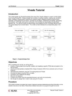
Vivado tutorial - Xilinx
www.xilinx.comdevice and using the Verilog HDL. Use the provided tutorial.v and tutorial.xdc files from the sources directory. 1-1-1. Open Vivado by selecting Start > All Programs > Xilinx Design Tools > Vivado 2013.3 > Vivado 2013.3 1-1-2. Click Create New Project to start the wizard. You will see Create A New Vivado Project dialog box. Click Next. 1-1-3.

Introduction to Verilog HDL
athena.ecs.csus.eduVerilog •Verilog was developed by Gateway Design Automation as a proprietary language for logic simulation in 1984. •Gateway was acquired by Cadence in 1989 •Verilog was made an open standard in 1990 under the control of Open Verilog International. •The language became an IEEE standard in 1995 (IEEE STD 1364) and was updated in 2001 and

IEEE Std 1364-1995) EEE Standards IEEE Standards Design ...
inst.eecs.berkeley.eduThe Verilog ¤ Hardware Description Language (HDL) is defined in this standard. Verilog HDL is a formal notation intended for use in all phases of the creation of electronic systems. Be-cause it is both machine readable and human readable, it supports the development, verification,

Verilog-A Language Reference Manual
www.siue.eduVerilog-A HDL Overview 1.1 Overview This Verilog-A Hardware Description Language (HDL) language reference manual defines a behavioral language for analog systems. Verilog-A HDL is derived from the IEEE 1364 Verilog HDL specification. This document is intended to cover the definition and semantics of Verilog-A HDL as proposed by Open Verilog ...