Verilog Tutorial - UMD
The standard, which combined both the Verilog language syntax and the PLI in a single volume, was passed in May 1995 and now known as IEEE Std. 1364−1995. After many years, new features have been added to Verilog, and new version is called Verilog 2001. This version seems to have fixed lot of problems that Verilog 1995 had. This version is
Download Verilog Tutorial - UMD

Information
Domain:
Source:
Link to this page:
Documents from same domain
Exception and Interrupt Handling in ARM
classweb.ece.umd.eduException and interrupt handling is a critical issue since it affect directly the speed of the system and how fast does the system respond to external events and how does it deal with more than one external event at the same time by assigning priorities to these events.
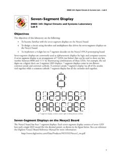
Seven-Segment Display - UMD
classweb.ece.umd.eduA 7-segment display contains seven light emitting diodes (LEDs) Seven-Segment Displays on the Nexys2 Board!e Nexys2 board has four 7-segment displays. Each seven-segment display consists of seven LED bars and a single LED round (for the decimal point), as shown in the figure below. You can reference
Plasma Enhanced Chemical Vapor Deposition (PECVD)
classweb.ece.umd.eduChemical Vapor Deposition for Microelectronics Principles, Technology, and Applications. Park Ridge, NJ: Noyes Publications, 1987. QUESTIONS? Title: Microsoft PowerPoint - PECVD Presentation.ppt Author: nganig Created Date: 10/24/2007 2:14:06 PM ...
Damascene Process and Chemical Mechanical Planarization
classweb.ece.umd.eduOct 17, 2011 · Damascene Process Steps Damascene is an additive process Firstly, the dielectric is deposited Secondly, the dielectric is etched according to the defined photoresist pattern, and then barrier layer is deposited Thirdly, copper is deposited Optimum way of copper deposition is electroplating Copper electrodeposition is a two step process

Seven-Segment Display - UMD
classweb.ece.umd.eduENEE 245: Digital Circuits & Systems Lab — Lab 8 Nexys2 seven-segment displays !e Nexys2 board uses the common anode method for its displays. !is means that all the anodes are tied together and connected through a pnp transistor to +3.3V, as shown in Figure 7.3. A

Low-pressure CVD and Plasma- Enhanced CVD - UMD
classweb.ece.umd.eduPlasmas are divided into two groups; cold (also called non-thermal) and thermal. In thermal plasmas, electrons and particles in the gas are at the same temperature; however, in cold plasmas the electrons have a much higher temperature than the neutral particles and ions. Therefore, cold plasmas can utilize
Interrupt handling - UMD
classweb.ece.umd.eduinterrupt can then be serviced by an interrupt service routine (ISR). Interrupt handling 5 Figure 1.3 Example of a simple interrupt system The interrupt handler is the routine that is executed when an interrupt occurs and an ISR is a routine that acts on …
Related documents

SystemVerilog Ports & Data Types For Simple, Efficient and ...
www.sunburst-design.comVerilog-2001 internal wire declaration requirements are discussed in the next section. 4. Verilog-2001: `default_nettype none As noted in section 2, 1-bit internal wires driven from continuous assignments had to be explicitly declared in Verilog-1995. Verilog-2001 removed this inconsistency from the Verilog language. Verilog-2001 also ...
Simulating Verilog RTL using Synopsys VCS
inst.eecs.berkeley.eduSep 12, 2010 · compilation errors and warnings. Since you will be making use of various Verilog-2001 language features, you need to set the +v2k command line option so that VCS will correctly handle these new constructs. Verilog allows a designer to specify how the abstract delay units in their design map into real time units using the ‘timescale compiler ...
Verilog-2001 Quick Reference Guide - Sutherland HDL
sutherland-hdl.comVerilog HDL Quick Reference Guide 2 1.0 New Features In Verilog-2001 Verilog-2001, officially the “IEEE 1364-2001 Verilog Hardware Description Language”, adds several significant enhancements to the Verilog-1995 standard. • Attribute properties (page 4) • Generate blocks (page 21) • Configurations (page 43)

IEEE Standard for Verilog Hardware Description Language
www.eg.bucknell.edu(Revision of IEEE Std 1364-2001) IEEE Standard for Verilog® Hardware Description Language Sponsor Design Automation Standards Committee of the IEEE Computer Society Abstract: The Verilog hardware description language (HDL) is defined in this standard. Verilog HDL is a formal notation intended for use in all phases of the creation of electronic ...

Appendix A. Verilog Code of Design Examples - Springer
link.springer.comAppendix A. Verilog Code of Design Examples The next pages contain the Verilog 1364-2001 code of all design examples. The old style Verilog 1364-1995 code can be found in [441]. The synthesis results for the examples are listed on page 881. //***** // IEEE STD 1364-2001 Verilog file: example.v // Author-EMAIL: Uwe.Meyer-Baese@ieee.org

IEEE Std 1364-1995) EEE Standards IEEE Standards Design ...
inst.eecs.berkeley.edueffort to get a much better Verilog standard in IEEE Std 1364-2001. Objective of the IEEE Std 1364-2001 effort The starting point for the IEEE 1364 Working Group for this standard was the feedback received from the IEEE Std 1364-1995 users worldwide. It was clear from the feedback that users wanted improvements in all aspects of the language.
Verilog 1 - Fundamentals
cseweb.ucsd.edutype in Verilog Z High impedance, floating X Unknown logic value 1 Logic one 0 Logic zero Value Meaning An X bit might be a 0, 1, Z, or in transition. We can ... ANSI C Style Verilog-2001 Syntax module adder( input [3:0] A, input [3:0] B, output cout, output [3:0] sum ); Alternate syntax adder A B cout sum 4 4 4 .

Verilog HDL Coding - Cornell University
people.ece.cornell.eduSection 7 Verilog HDL Coding 7.1 Introduction The Verilog HDL coding standards pertain to virtual component (VC) generation and deal with naming conventions, documentation of the code and the format, or style, of the code. Conformity to these standards

SystemVerilog vs Verilog in RTL Design
academic.csuohio.eduVerilog is intended mainly for the gate‐ and register‐transfer‐level design and modeling. It became the IEEE Standard 1364‐1995 in 1995 (referred to as Verilog‐95), revised in 2001 (referred to as Verilog‐ 2001) and again in 2005 (referred to as Verilog‐2005).