
WIRE HARNESS INSTALLATION INSTRUCTIONS
easiest to install truck wire harness on the market. It is designed for easy installation, even if you have no electrical experience. The fuse block, can be easily mounted in the factory location. The fuse block, voltmeter, fuel gauge, oil pressure gauge, temperature gauge, turn signal lights, high beam switch and dash
Download WIRE HARNESS INSTALLATION INSTRUCTIONS

Information
Domain:
Source:
Link to this page:
Documents from same domain

Manual #90567 For Installing: Part #30830
www.painlessperformance.com7 Figure 1 C.S.I. Harness Schematic CONTENTS OF THE PAINLESS C.S.I. WIRE HARNESS KIT Refer to the list below to take inventory of all the parts in the kit. If anything is found to be
For Installing: #10127 Customizable Mopar Chassis …
www.painlessperformance.comWire Harness Installation Instructions For Installing: #10127 Customizable Mopar Chassis Harness 21 Circuit Manual #90542

Wire Harness Installation Instructions - Painless …
www.painlessperformance.comWire Harness Installation Instructions For Installing: #20110 Classic Customizable Chevy II/Nova 1966-67 Harness 21 Circuit Manual #90522

Wire Harness Installation Instructions - Painless …
www.painlessperformance.comWire Harness Installation Instructions For Installing: Part #20120 22 Circuit Ford Mustang (1965- 1966) Manual #90526

Wire Harness Installation Instructions - Painless …
www.painlessperformance.comWire Harness Installation Instructions For Installing: #10101 Classic Customizable Harness-GM Keyed Column-21 Circuit #10102 Classic Customizable Harness-Non GM Keyed Column-21 Circuit
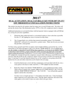
175 o OFF THERMOSTAT INSTALLATION …
www.painlessperformance.com1 2501 Ludelle Street Fort Worth, Texas 76105 . 817-244-6212 phone . 817-244-4024 fax . 800-423-9696 Tech . E-Mail: painless@painlessperformance.com . Web: www.painlessperformance.com

Manual #90560 For Installing: #10111 Direct Fit Jeep YJ ...
www.painlessperformance.com7 Sections are divided into subsections and Paragraphs.Throughout these instructions, the Figure numbers refer to pictures and the Diagram numbers refer to illustrations.Figure numbers correspond to the Section number the are covered in. Always pay special and careful

HIGH AMPERAGE ALTERNATOR KIT (140-190 AMPS)
www.painlessperformance.com2 onto the output post of the alternator. This connection can be seen in Figure 1 on the next page and can be accomplished one of two ways: #1 Install each wire separately • Slide the rubber boot and/or a piece of the smaller sized heat shrink onto the wire found in the kit.

Wire Harness Installation Instructions
www.painlessperformance.com3.0 CONTENTS OF THE PAINLESS WIRE HARNESS KIT Refer to the list below to take inventory of all the parts in the kit. If anything is found to be missing, contact the dealer the kit was purchased

80230 - painlessperformance.com
www.painlessperformance.comPainless Performance Limited Warranty and Return Policy Chassis harnesses and fuel injection harnesses are covered under a lifetime warranty. All other products manufactured and/or sold by Painless Performance
Related documents

Diesel Engines for NFPA-20 Fire Protection Applications
www.saltech.co.ilNFPA 20 –Fuel Tank Arrangement •The fuel tank is sized for 5.07 liter/kW (1 gal/HP) plus 10% (5% for expansion and 5% for sump). •The fuel tank shall be reserved exclusively for the fire pump diesel engine. •There shall be one fuel tank per engine.

NEW VINTAGE INSTRUMENT AND GAUGE KIT …
newvintageusa.comFuel level: 240-33 w/ sender, 0-90, 73-10, 0-30 The fuel gauge range (ohms) must match sender 1. Locate suitable positions foryour gauges. The gauges fit in a 4-3/8" and/or 3-3/8" holes. Take note of the anti-rotation notches and add this feature where required.-2-

GM LS Engine Gauges Installation Guide - Autometer
www.autometer.comgauge mounting location to the radiator hose adapter installation point. Radiator hose adapters also come with the 3/8” npt adapter, so an additional #2263 is not necessary for this installation type. The 2277 adapter requires a 3/4" wrench, and the 2252 sender requires a 13mm wrench. Be careful to only tighten the adapter into the head until the

Aboveground Tank Application and Installation Guidelines
www.oregon.govpercent of tank capacity by providing an audible or visual alarm signal, providing a tank level gauge marked at 90 percent of tank capacity, or other approved means, and Automatically shut off the flow of fuel to the tank when the quantity of liquid in the tank reaches 95
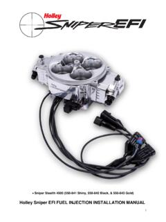
Holley Sniper EFI FUEL INJECTION INSTALLATION MANUAL
documents.holley.comApr 30, 2018 · fuel pump in the tank results in quieter operation, less chance of cavitation and a reduction in pump temperature. If mounting the pump in the tank is not an option, install the pump as close as possible to the tank. Within 2-feet of sending unit is recommended. Once the fuel system is installed checking the fuel pressure on the inlet side of the
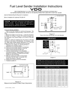
Fuel Level Sender Installation Instructions
www.vdo-gauges.comParts of the Fuel Level Sender Unit to be Ad Fuel Level Sender Installation: Refer to the VDO catalog for matching fuel gauges. The unit can be adjusted to read accurately in tanks from 6" to 23" deep. Diagram B I. Measure the depth of your fuel tank. Locate this dimension in Column "A" of Table 1. Column "B" shows the length from
Analog / Digital Gauge System INSTALLATION AND …
www.dakotadigital.comMAN 650314:D 7 ACC. POWER Connect the ACC. POWER terminal to accessory +12V power from the fuse panel or vehicle wiring harness. This terminal should have power when the key is on or in the ‘accessory’
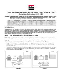
FUEL PRESSURE REGULATORS P/N 12-881, 12-882, 12-886, & …
documents.holley.comFUEL PRESSURE GAUGE (S) WHEN ADJUSTING THE FUEL PRESSURE REGULATOR. NOTE: On carbureted systems, any change made in fuel pressure will change the fuel bowl float level requirements. A readjustment in fuel bowl levels will be required for proper operation of the fuel system. Technical Service: 1-866-464-6553 www.holley.com

HELP?: GENERAL APPLICATION: Installation Instructions ...
www.stewartwarner.comFUEL LEVEL GAUGE WIRING (Figure 4): 1. Disconnect negative (-) battery cable. 2. Using 18-ga. wire, connect the (G) terminal to a clean (rust/paint-free) Figure 4ground. 3. Using 18 gauge wire, connect the (I) terminal to a switched +12V source. 4. Using 18-gauge wire, connect the (S) sender terminal of the gauge to the fuel level sender. 5.

WEBER CARBURETOR CONVERSION KIT INSTALLATION GUIDE
www.quadratec.comwhile maintaining both reliability and fuel efficiency. This installation guide covers vehicle preparation, old carburetor removal, carburetor installation, and new carburetor adjustments. A trouble-shooting guide is supplied. Before installation please read this guide thoroughly. If you have any questions please call our Toll Free Technical ...