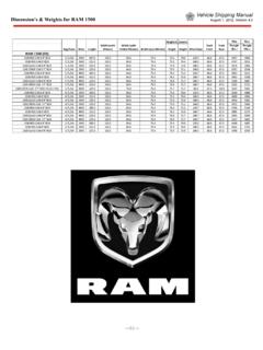
Transcription of Figure 2 Wire Color Code Charts Z - Grounds (Varies ...
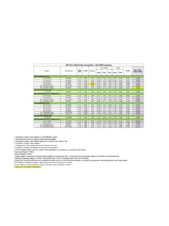
1 Wiring Code Identification Information WIRE CODE IDENTIFICATION Each wire shown in the diagrams contains a code ( ) which identifies the main circuit, part of the maincircuit, gauge of wire, and Color . The Color is shown as atwo-letter code, which can be identified by referring tothe Wire Color Code Chart (Fig. 2). Figure 1 Wire Color Code Identification CIRCUIT IDENTIFICATION All circuits in the diagrams use an alphanumeric code toidentify the wire and its function (Fig. 3). To identify which circuit code applies to a system; refer to theCircuit Identification Code Chart. This chart shows the main circuits only and does not show the secondary codes that may apply to some models.
2 Figure 2 Wire Color Code Charts Figure 3 Circuit Identification Color OF WIRE(Light Blue with Yellow Tracer)GAUGE OF WIRE(18 Gauge)PART OF MAIN CIRCUIT (Varies Depending on Equipment)MAIN CIRCUIT IDENTIFICATIONALB/YL218 ColorCodeColorColorCodeColorBKBLACKORORA NGEBLBLUEPKPINKBRBROWNRDREDDBDARKBLUETNT ANDGDARKGREENVTVIOLETGYGRAYWTWHITELBLIGH TBLUEYLYELLOWLGLIGHTGREENBase Wire Color Code ChartCIRCUITFUNCTIONA- Battery FeedB- Brake ControlsC-Climate Controls, EBL, Heated Mirror, Windshield and SeatD-Diagnostic Circuits, Communications,AntennasE- Dimming Illumination CircuitsF- Switched Ignition FeedsG-Gauges, Displays, Monitoring, Body Sensors, Resistive Mux'd SwitchesH- OpenI- Not UsedJ- OpenK- Power Train Control ModuleL- Exterior Lighting.
3 Headlamp LevelingM- Interior and Courtesy LightingN- Fuel Pump, Radiator FanO- Not UsedP-Power Option, Seats, Recliner, Lumbar, Mirrors, Door LocksQ-Power Options, Windows, Vents,Sunroof, Tops, Trunk, Liftgate, Sliding DoorsR- Restraint SystemsS- Suspension/SteeringT-Starter, Transmission, Transaxle, Transfer CaseU- OpenV- Speed ControlW- Washer, WiperX- Sound Systems, HornY- OpenZ- GroundsColorCodeColorColorCodeColorBRBRO WNORORANGEDBDARK BLUETNTANDGDARK GREENVTVIOLETGYGRAYWTWHITELBLIGHT BLUEYLYELLOWLGLIGHT GREENT racer Wire Color Code Chart Wiring Code Identification Information CONNECTORS Connectors shown in the diagrams are identified using the international standard arrows for male and femaleterminals (Fig.)
4 4). A connector identifier is placed next to the arrows to indicate the connector number (Fig. 4). For viewing connector pin outs, with two terminals or greater, refer to section 8W-80. This section identifies the connector by number and provides terminal numbering, circuit identification, wire colors andfunctions. All connectors are viewed from the terminal end unless otherwise specified. To find the connector location in the vehicle, refer to section 8W-90. This section uses the connector identification number from the wiring diagrams to provide a Figure number reference. TAKE OUTS The abbreviation T/O is used in the component locationsection to indicate a point in which the wiring harness branches out to a component.
5 ELECTROSTATIC DISCHARGE (ESD) SENSITIVE DEVICES All ESD sensitive components are solid state and asymbol (Fig. 5) is used to indicate this. When handlingany component with this symbol, comply with the following procedures to reduce the possibility of electrostatic charge buildup on the body and inadvertent discharge into the component. If it is not known whetherthe part is ESD sensitive, assume that it is. 1)Always touch a known ground before handling thepart. This should be repeated while handling the partand more frequently after sliding across a seat,sitting down from a standing position or walking )Avoid touching electrical terminals of the part, unlessinstructed to do so by a written )When using a voltmeter, be sure to connect theground lead )Do not remove the part from its protective packinguntil it is time to install the )
6 Before removing the part from its package, groundthe package to a known good ground on the 4 Electrostatic Discharge Symbol Figure 5 Electrostatic Discharge Symbol Wiring Code Identification Information WIRING GUIDELINES FOR 2013 RAM TRUCK AFTERMARKET/BODY BUILDERS 1. IntroductionThese guidelines are intended as an aid in wiring design. It is not an all-inclusive list or a substitute forcommon sense. It is to be used as a supplement to existing good design practices and information is in the Referenced Publications section. Performing a Failure Mode and Effects Analysis (FMEA) on each completed wiring design is a good practice to confirm the integrity of the design.
7 This document will be revised periodically, based on advances in technology andoperating practices. SystemA. Modification to the existing vehicle wiring should be done only with extreme caution. The effects on the completed vehicle electrical system must be considered. Any additional circuitry should be evaluated to ensure that adequate circuitprotection provisions will be in place and thatfeedback loops will not be created. B. The following affects the selection of wire gauge for a particular application: Wire size selection is affected by circuit protection requirements, power distribution requirements and mechanical handlingrequirements Wire size selection is affected by long-range heat aging characteristics resulting from current loading C.
8 Circuit Protection When adding loads to a base vehicle s protected circuit; be sure that the total electrical load through the base vehicle fuse or circuit breakeris less than the derated device rating. The total electrical load is the sum of the base vehicle circuit current requirement added to the add-oncomponent(s) current requirements. Confirm theload with an ammeter. DO NOT increase the rating of a factory-installed fuse or circuit Any added circuitry must be protected by either the base vehicle fuse or circuitbreaker or by a similar device installed by the body builder. In-line fuses should bereadily accessible All battery circuits, except the starter motor,must have circuit protection Protections devices for high current loads such as a winch or snowplow motor must beconnected directly to the vehicle battery andnot to the vehicle power distribution centeror other downstream components.
9 Circuit protection devices are designed toprotect the wiring. They may not necessarily protect other components in the event of a shortcircuit. 3. Harness RoutingA. Connectors should be readily accessible, where feasible, to permit ease of installation and serviceability. Accessibility to connectors is gooddesign practice. Examples include fuse blocks,relays, modules, electrical components, junctionblocks and ground blocks. B. Provide sufficient wire lengths to permit wireharness serviceability. However, excess lengths should be kept to a minimum to prevent: trapping and pinching during assembly; poor fitand finish; and buzzes, squeaks and rattles.
10 C. Circuits attached to parts or structures that havedynamic (moving) properties must consider adequate slack and strain relief to preventdamage. A few examples are the engine block,door and liftgate harness, shocks, struts and tilt steering columns. Endurance testing must beperformed to ensure that designs meet life testcriteria. D. Wiring assemblies must not be within one inch(25 mm) of any hot surface or moving mechanism. Movement due to engine rocking will require a greater distance than one discretion must be used todetermine if heat-protection materials are needed to protect the wiring assembly. The useof abrasion-protection materials (convolutedtubing, fiberglass loom, asphalt loom, friction tape, etc.)