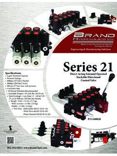
Transcription of LS DIRECTIONAL CONTROL VALVES INSTALLATION & USER …
1 LS DIRECTIONAL CONTROL VALVES . INSTALLATION & USER GUIDE. SPECIFICATIONS: Rated 0-18 gpm ( lpm). 30 Micron filtration recommended. Rated for 3000 psi (207 bar). Standard port sizes. Weighs 5-1/2 lbs. ( kg). Inlet/Outlet 3/4 NPT and work ports 1/2 NPT. MOUNTING, ADJUSTMENT & ASSEMBLY INSTRUCTIONS: Mounting Valve can be mounted in any orientation. Valve must be mounted on a flat surface. Special attention should be paid to not bend or twist the casting when mounting. Doing so may cause the valve to fail. Relief Adjustment Relief setting is factory preset to 2000 psi, unless otherwise noted within model code. Relief valve can be set anywhere within the range of 500 psi to 3000psi. To adjust relief pressure : First, remove chrome hex plug next to the inlet port with a 7/8 combination wrench, etc.
2 You will then have access to the relief set screw. Turning this screw with a 5/16 allen wrench clockwise turn will increase pressure approximately 200psi. Hydraulic Kick-out Adjustment The SH & SHA models have an adjustable single hydraulic kick out preset to 800- 1000 psi. The HHA model comes equipped with a double hydraulic kick out preset to 800-1000 psi. To adjust kick-out pressure : Locate jam nut, and set screw on the spool action cap. (Opposite valve's handle). Loosen jam nut, and turn set screw. Turning set screw clockwise with a 1/8 allen wrench will decrease kick-out pressure , while turning it counter clockwise will increase kick-out pressure on the SH version of valve.
3 Handle Assembly Regardless of handle style, the handle retainer will be installed on valve from factory. Unless specified, the retainer's placement is defaulted so the handle points up when the valve is placed on a flat surface. To change this, prior to handle INSTALLATION , the screws holding the retainer must be removed and the retainer can then be rotated around the spool 180 . L-Style Handle: Recognized by the single hole in the end of the spool, place the ball end of the handle in the spool and then join the handle and the retainer using the supplied pin. J-Style Handle: Recognized by the single slot in the end of the spool, first, place a pin thru the bracket welded to the retainer and secure with a pin clip.
4 Next, place the C-notch of the handle over and onto the pin. Finally, align the hole of the handle with the hole on the spool and secure both together using the second pin and clip. FREQUENTLY ASKED QUESTIONS: Q: Can I plumb another valve downstream from this valve, using the outlet of this valve? A: No. The outlet of this valve should be plumbed back to tank. Q: Which port has Hydraulic Kick-out ? A: The A' port (See Dimensional Data) will, when handle is engaged in a detent position until the kick-out pressure is reached, at which point the valve will kick-out of detent into the neutral position. Q: What kits are available for this valve? A: There is a replacement seal kit per valve.
5 VALVES ending in SH uses LS-RK, valve ending in SHA uses LSJRSH-K, valve ending in HHA uses LSJRHH-K. There are also a number of different kits available for this valve depending on the spool action, and handle option the valve is equipped with. Please contact factory for specific kit numbers relating to different spool actions, and handle options. 04/14. FREQUENTLY ASKED QUESTIONS cont'd: Q: Can I paint the valve? A: Painting VALVES is acceptable as long as the following precautions are taken: 1- All ports must be plugged 2- Spool must be masked or taped off completely. Any paint on the spool will cause leakage when it chips off. Warranty is void if any valve is returned with paint on the spool.
6 Q: What is the typical use of the Hydraulic Kick-out ? A: The typical set-up for using hydraulic kick-out is the retraction of a log splitter cylinder. In this case, the cylinder can retract unmanned while another log is being loaded onto the splitter. GENERAL INFORMATION: Pipe Thread Sealant - Warranty is void when Teflon tape is used to seal pipe threads. This is because Teflon tape is a friction reducing agent which allows customers to over-torque fittings. We recommend using a sealant that does not include friction reducing agents Lead Plate. ADJUSTABLE RELIEF (2000 PSI (138 BAR) FACTORY SETTING). DIMENSIONAL DATA: " [ ]. " [ ]. " [ ]. A PORT. " [ ]. B PORT. " [ ]. " [ ]. " [ ].
7 " [ ]. " [ ]. " [ ]. " [ ] " [ ] " [ ]. " [ ] " [ ]. 3X " [ ]. FLOW & pressure INFORMATION: pressure vs. Flow for LS Relief (R) pressure Drop vs. Flow Flow (lpm) Flow (lpm). 3500 45 B505 Spring 3000 40 35 pressure Drop (bar). pressure Drop (psi). 2500 P to A or B, and A or B to T. pressure (bar). pressure (psi). 30 2000 25 1500 20 Neutral Flow (T4 Spool). 15 1000 10 500 5 Relief is set at 6 gpm 0 0 Flow (gpm) Flow (gpm). 04/14. SPOOL SCHEMATIC: A B A B. P T P T. Tandem Center 4-way (T4) - Powers cylinder or Open Center 4-way (O4) - All of the ports are motor in both directions. Pump unloads to tank connected to tank when the spool is in neutral. when spool is in neutral. Cylinder or motor Allows cylinder to move or motor to rotate blocked when spool in neutral.
8 When spool is in neutral. A B. P T. Closed Center 4-way (C4)- All ports are blocked in neutral. Blocks cylinder or motor in neutral. Required for use with pressure compensated pump. TYPICAL INSTALLATION SCHEMATIC: "B" PORT. LS VALVE. "A" PORT. LOG. CYLINDER CAP CYLINDER ROD. END END. RETRACT. EXTEND. NOTE: PULLING LEVER HANDLE WILL PRESSURIZE "B" PORT. AND EXTEND CYLINDER. PUSHING LEVER HANDLE WILL PRESSURIZE "A" PORT. AND RETRACT CYLINDER. LEVER HANDLE WILL KICK BACK TO NEUTRAL. WHEN CYLINDER IS FULLY RETRACTED. 04/14. SAFETY PRECAUTIONS: It is the purchaser's responsibility to determine the suitability of any Brand Hydraulics Co. product for an intended application, and to ensure that it is installed in accordance with all federal, state, local, private safety and health regulations, codes and standards.
9 Due to the unlimited variety of machines, vehicles and equipment on which our products can be used, it is impossible for Brand Hydraulics Co. to offer expert advice on the suitability of a product for a specific application. It is our customer's responsibility to undertake the appropriate precautions, testing and evaluation to prevent injury to the end-user. Overpressure may cause sudden and unexpected failure of a component in the hydraulic system, resulting in serious personal injury or death. Always use a gauge when adjusting a relief valve. 04/14.