Transcription of NCP1216, NCP1216A - PWM Current-Mode Controller for …
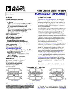
1 Semiconductor Components Industries, LLC, 2016 May, 2016 Rev. 161 Publication Order Number:NCP1216/DNCP1216, NCP1216 APWM Current-ModeController for high -PowerUniversal Off-Line SuppliesHoused in a SOIC 8 or PDIP 7 package, the NCP1216 representsan enhanced version of NCP1200 based controllers. Due to its highdrive capability, NCP1216 drives large gate charge MOSFETs, whichtogether with internal ramp compensation and built in frequencyjittering, ease the design of modern AC DC an internal structure operating at different fixed frequencies,the Controller supplies itself from the high voltage rail, avoiding theneed of an auxiliary winding. This feature naturally eases the designertask in some particular applications, battery chargers or TV mode control also provides an excellent input audiosusceptibility and inherent pulse by pulse control.
2 Internal rampcompensation easily prevents sub harmonic oscillations from takingplace in continuous conduction mode the current setpoint falls below a given value, the outputpower demand diminishes, the IC automatically enters the so calledskip cycle mode and provides excellent efficiency at light this occurs at a user adjustable low peak current, no acousticnoise takes NCP1216 features an efficient protective circuitry, which inpresence of an over current condition disables the output pulses whilethe device enters a safe burst mode, trying to restart. Once the defaulthas gone, the device auto No Auxiliary Winding Operation Current Mode Control with Adjustable Skip Cycle Capability Internal Ramp Compensation Limited Duty Cycle to 50% ( NCP1216A Only) Internal ms Soft Start ( NCP1216A Only)
3 Built In Frequency Jittering for Better EMI Signature Auto Recovery Internal Output Short Circuit Protection Extremely Low No Load Standby Power 500 mA Peak Current Capability Fixed Frequency Versions at 65 kHz, 100 kHz, 133 kHz Internal Temperature Shutdown Direct Optocoupler Connection SPICE Models Available for TRAN sient and AC Analysis Pin to Pin Compatible with NCP1200 Series These are Pb Free and Halide Free DevicesTypical Applications high Power AC DC Converters for TVs, Set Top Boxes, etc. Offline Adapters for Notebooks Telecom DC DC Converters All Power SuppliesSOIC 8D SUFFIXCASE 751 MARKINGDIAGRAMSPDIP 7P SUFFIXCASE 626 BXXXXXXXXXAWLYYWWG1 XXXXXX = Specific Device CodeA= Assembly LocationWL, L= Wafer LotYY, Y= YearWW, W = Work WeekG or G= Pb Free PackagePIN CONNECTIONS1 Adj8HV2FB3CS4 Gnd7NC6 VCC5 DrvSee detailed ordering and shipping information in the orderinginformation section on page 16 of this data MARKING AND ORDERING , InputFosc = 35kHzHVVccDrvGNDAdjFBCSNCP1216 EMIF ilter12345678 RsenseRcomp+++*See Application SectionFigure 1.
4 Typical Application Example PIN FUNCTION DESCRIPTIONPin NameFunctionPin Description1 AdjAdjust the Skipping Peak CurrentThis pin lets you adjust the level at which the cycle skipping processtakes place. Shorting this pin to ground, permanently disables the skipcycle the Peak Current SetpointBy connecting an Optocoupler to this pin, the peak current setpoint isadjusted accordingly to the output power Sense InputThis pin senses the primary current and routes it to the internal com-parator via an By inserting a resistor in series with the pin, youcontrol the amount of ramp compensation you Ground 5 DrvDriving PulsesThe driver s output to an external the ICThis pin is connected to an external bulk capacitor of typically 22 This un connected pin ensures adequate creepage the VCC from the LineConnected to the high voltage rail, this pin injects a constant currentinto the VCC bulk.
5 VHV12345678 DrvGNDNCC urrentSenseAdjFBSkip Cycle VOverload?Fault Duration20 k19 kClock Jittering57 k25 k96 k25 k5 VFigure 2. Internal Circuit Architecture + +Pull up ResistorUVLO high and LowInternal RegulatorHV Current SourceQ Flip FlopDCmax = 75%Reset65 kHz100 kHz133kHzRampCompensation +Vref220 $500 mAVCCI nternal VCC1 ms SS** Available for A version RATINGSR atingSymbolValueUnitPower Supply Voltage, VCC PinVCC16 VMaximum Voltage on Low Power Pins (except Pin 8 and Pin 6) to 10 VMaximum Voltage on Pin 8 (HV), Pin 6 (VCC) Decoupled to Ground with 10 mF500 VMaximum Voltage on Pin 8 (HV), Pin 6 (VCC) Grounded450 VMinimum Operating Voltage on Pin 8 (HV)28 VMaximum Current into all Pins except VCC (Pin 6) and HV (Pin 8) when 10 V ESD Di-odes are Resistance Junction to Air, PDIP 7 VersionThermal Resistance Junction to Air, SOIC 8 VersionRqJ ARqJ A100178 C/WMaximum Junction TemperatureTJMAX150 CTemperature ShutdownTSD155 CHysteresis in Shutdown30 CStorage Temperature Range 60 to +150 CESD Capability, HBM Model (All Pins except VCC and HV) Capability, Machine Model200 VStresses exceeding those listed in the Maximum Ratings table may damage the device.
6 If any of these limits are exceeded, device functionalityshould not be assumed, damage may occur and reliability may be This device series contains ESD protection rated using the following tests:Human Body Model (HBM) 2000 V per JEDEC Standard JESD22, Method Model (MM) 200 V per JEDEC Standard JESD22, Method , CHARACTERISTICS (For typical values TJ = 25 C, for min/max values TJ = 40 C to +125 C, Maximum TJ = 150 C, VCC = 11 V unless otherwise noted.)CharacteristicPinSymbolMinTypMaxU nitDYNAMIC SELF SUPPLYVCC Increasing Level at which the Current Source Turns (Note 1)VVCC Decreasing Level at which the Current Source Turns (Note 1)VVCC Decreasing Level at which the Latchoff Phase IC Consumption, Latchoff Phase, VCC = VNCP1216 NCP1216A6 ICC3250320mAInternal IC Consumption, No Output Load on Pin 5, FSW = 65 kHz0 C TJ +125 C 40 C TJ +125 C6 ICC199011101245mAInternal IC Consumption, No Output Load on Pin 5, FSW = 100 kHz0 C TJ +125 C 40 C TJ +125 C6 ICC1102511801285mAInternal IC Consumption, No Output Load on Pin 5, FSW = 133 kHz0 C TJ +125 C 40 C TJ +125 C6 ICC1106012001290mAInternal IC Consumption, nF Output Load on Pin 5, FSW = 65 kHz0 C TJ +125 C 40 C TJ +125 IC Consumption, nF Output Load on Pin 5, FSW = 100 kHz0 C TJ +125 C 40 C TJ +125 IC Consumption, nF Output Load on Pin 5.
7 FSW = 133 kHz0 C TJ +125 C 40 C TJ +125 STARTUP CURRENT SOURCE (TJ > 0 C) high voltage Current Source, VCC = 10 (Note 2) voltage Current Source, VCC = 0 OUTPUTO utput Voltage Rise time @ CL = nF, 10 90% of a 12 V Output Signal5Tr60nsOutput Voltage Fall time @ CL = nF, 10 90% of a 12 V Output Signal5Tf20nsSource Resistance5 ROH152035 WSink COMPARATOR (Pin 5 Unloaded)Input Bias Current @ V Input Level on Pin Internal Current Internal Current Setpoint for Skip Cycle Operation3 ILskip330mVPropagation Delay from Current Detection to Gate OFF State3 TDEL80130nsLeading Edge Blanking Duration3 TLEB220nsProduct parametric performance is indicated in the Electrical Characteristics for the listed test conditions, unless otherwise noted.
8 Productperformance may not be indicated by the Electrical Characteristics if operated under different and VCCON min max always ensure an hysteresis of Minimum value for TJ = 125 , CHARACTERISTICS (continued) (For typical values TJ = 25 C, for min/max values TJ = 40 C to +125 C, Maximum TJ = 150 C, VCC = 11 V unless otherwise noted.)CharacteristicPinSymbolMinTypMaxU nitINTERNAL OSCILLATOR (VCC = 11 V, Pin 5 Loaded by kW)Oscillation Frequency, 65 kHz Version0 C TJ +125 C 40 C TJ +125 Frequency, 100 kHz Version0 C TJ +125 C 40 C TJ +125 CfOSC9086100100110120kHzOscillation Frequency, 133 kHz Version0 C TJ +125 C 40 C TJ +125 CfOSC120110133133146160kHzBuilt in Frequency Jittering in Percentage of fOSCfjitter Duty SECTION (VCC = 11 V, Pin 5 Loaded by kW)Internal Pullup Resistor2 Rup20kWPin 2 (FB) to Internal Current Setpoint Division Ratio CYCLE GENERATIOND efault Skip Mode 1 Internal Output Impedance1 Zout25kWINTERNAL RAMP COMPENSATIONI nternal Ramp Level @ 25 C (Note 3)
9 Ramp Resistance to CS Pin3 Rramp19kWProduct parametric performance is indicated in the Electrical Characteristics for the listed test conditions, unless otherwise noted. Productperformance may not be indicated by the Electrical Characteristics if operated under different A MW resistor is connected to the ground for the , ( C)Figure 3. high Voltage Pin Leakage Current 250255075100125HV PIN LEAKAGE CURRENT @ 500 V(mA)Figure 4. VCCOFF vs. 500255075100125 TEMPERATURE ( C)VCCOFF (V)Figure 5. VCCON vs. 500255075100125 VCCON (V)TEMPERATURE ( C)0600800100012001400 500255075100125 TEMPERATURE ( C)ICC1 (mA)Figure 6. ICC1 (@ VCC = 11 V) vs. Temperature65 kHz133 kHz100 500255075100125 TEMPERATURE ( C)ICC2 (mA)133 kHz100 kHz65 kHzFigure 7.
10 ICC2 vs. Temperature507090110130150 250255075100125133 kHz100 kHz65 kHzFOSC (kHz)TEMPERATURE ( C)Figure 8. Switching Frequency CHARACTERISTICS60 50 25 25 25 25 50200400 NCP1216, 250255075100125 TEMPERATURE ( C)VCClatch (V)Figure 9. VCClatch vs. TemperatureFigure 10. ICC3 vs. Temperature0100200300400 250255075100125 TEMPERATURE ( C)ICC3 (mA)051015202530 250255075100125 DRIVER RESISTANCE (W)TEMPERATURE ( C)Figure 11. Drive Sink and Source Resistancevs. 250255075100125 TEMPERATURE ( C)CURRENT SENSE LIMIT (V)Figure 12. Current Sense Limit vs. Temperature ( C)Vskip (V)Figure 13. Vskip vs. 250255075100125 TEMPERATURE ( C)DUTY CYCLE (%)Figure 14. NCP1216 Max Duty Cycle 50 50 50 50 50 50 NCP1216, 250255075100125 TEMPERATURE ( C)Vramp (V)Figure 15.