Transcription of Generator Sizing Guide - Echo Group Inc
1 Generator Sizing Guide IMPORTANT NOTICE: This booklet is designed to familiarize estimators and installers with proper Sizing guidelines for residential and commercial generators . The information is not comprehensive, nor does it replace or supercede any material contained in any of the written documents shipped with the equipment. This booklet should only be used in conjunction with the Owner's Manual, Installation Manual and other technical documents shipped with each product. Always read all accompanying documentation carefully before attempting to install any Generator , transfer switch or related equipment. HOW TO USE THIS BOOKLET: Within this booklet, you will find electrical load information, plus an outline of Generator surge capability, fuel pipe Sizing , liquid propane tank Sizing , and UPS / Generator compatibility. The worksheet pages can be removed from the book and photocopied to create additional Onsite Estimating Sheets for use with individual jobs.
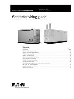
2 SAFETY INFORMATION: Proper Sizing of the Generator is crucial to the success of any installation and requires a good working knowledge of electricity and its characteristics, as well as the varying requirements of the electrical equipment comprising the load. When analyzing the electrical load, consult the manufacturer's nameplate on each major appliance or piece of equipment to determine its starting and running requirements in terms of watts, amps and voltage. When choosing the Generator output for commercial or industrial applications, select a rating that is approximately 20 to 25% higher than the peak load (for example, if the load is about 40 kilowatts, select a 50 kW genset). A higher rated Generator will operate comfortably at approximately 80% of its full capacity and will provide a margin of flexibility if the load increases in the future.
3 For safety reasons, Generac recommends that the backup power system be installed, serviced and repaired by a Generac Authorized Service Dealer or a competent, qualified electrician or installation technician who is familiar with applicable codes, standards and regulations. It is essential to comply with all regulations established by the Occupational Safety & Health Administration (OSHA) and strict adherence to all local, state and national codes is mandatory. Before selecting a Generator , check for municipal ordinances that may dictate requirements regarding placement of the unit (setback from building and/or lot line), electrical wiring, gas piping, fuel storage (for liquid propane or diesel tanks ), sound and exhaust emissions. 2. Generator S I ZIN G G U ID E. Table of Contents Placement Diagram - Air-cooled generators .. 4. Table 1 Motor Load Reference.
4 5. Table 2 Non-Motor Load Reference .. 6. Table 3 Surge Capability .. 7. Table 3A Protector Series .. 8. Natural Gas Installation .. 9. Table 4 Fuel Pipe Sizing Natural Gas .. 9. LP Vapor Installation .. 10. Table 5 Fuel Pipe Sizing LP Vapor .. 10. Table 6 LP Vapor (LPV) Tank Sizing .. 11. Table 7 Generator Fuel Consumption .. 11. UPS Generator Compatibility .. 12. UPS Sizing EXAMPLES .. 13. Typical Generator /Transfer Switch Combinations .. 14 15. NEC 700, 701, 702 Comparison .. 16. Electrical Formulas, Weights and Measures .. 18. Tear-out Worksheets: .. 19. Selected Circuit Load Calculator System Capacity Load Calculator 33. PLACEMENT DIAGRAM AIR-COOLED generators . D 5 ft ( m) C 5 ft ( m) E. 3 ft B ( m) A 3 ft ( m) B. 3 ft ( m). B F 001751. G. D. 001789. ID Description Comments A Top of Generator . B Front and end clearance Minimum clear distances cannot include shrubs, bushes, or trees.
5 C Rear clearance 18 in ( cm) minimum clearance per NFPA testing, labeling, and listing, unless state or local codes dictate otherwise. D Windows and openings No operable windows, doors, or openings in the wall are permitted within 5 ft ( m) from any point of the Generator . E Existing wall One-hour fire rated walls allow closer placement of the Generator set without approved enclosure. Confirm before installation. F Removable fence Removable fence panels for servicing cannot be placed less than 3 ft ( m) in front of the Generator . G Overhead clearance 5 ft ( m) minimum distance from any structure, overhang, or projections from the wall. DO NOT install under wooden decks or structures unless this distance is maintained. 4. Generator S I ZIN G G U ID E. TABL E 1 MOTOR LOAD REFERENCE. AC & Heat Pumps Running Load Starting Load Running Amps @ Amps @ Amps @ Amps @ LR Amps @ LR Amps @ LR Amps @ LR Amps Description Hp kW 240V 1 208V 3 240V 3 480V 3 240V 1 208V 3 240V 3 480V 3.
6 1 Ton 1 1 5 3 3 1 33 22 19 10. (12,000 BTU). 2 Ton 2 2 10 7 6 3 67 44 38 19. (24,000 BTU). 3 Ton (36,000 BTU) 3 3 15 10 8 4 100 67 58 29. 4 Ton 4 4 20 13 11 6 117 78 67 34. (48,000 BTU). 5 Ton 5 5 25 16 14 7 145 97 84 42. (60,000 BTU). Ton 37 24 21 11 219 146 126 63. (85,000 BTU). 10 Ton* 5 Hp (x2) 10 49 33 28 14 145 97 84 42. (120,000 BTU). 10 Ton 10 Hp 10 49 33 28 14 250 167 144 72. (120,000 BTU). 15 Ton* Hp (x2) 15 74 49 42 21 219 146 126 63. (180,000 BTU). 15 Ton 15 Hp 15 74 49 42 21 375 250 217 108. (180,000 BTU). 20 Ton* 10 Hp (x2) 20 98 65 57 28 250 167 144 72. (240,000 BTU). 20 Ton 20 Hp 20 n/a 65 57 28 500 333 289 144. (240,000 BTU). 25 Ton 25 25 n/a 82 71 35 625 416 361 180. (300,000 BTU). 30 Ton* 15 Hp (x2) 30 n/a 98 85 42 375 250 217 108. (360,000 BTU). 30 Ton 30 Hp 30 n/a 98 85 42 750 500 433 217. (360,000 BTU). 40 Ton* 20 Hp (x2) 40 n/a 131 113 57 500 333 289 144.
7 (480,000 BTU). 40 Ton 40 Hp 40 n/a 131 113 57 1000 666 577 289. (480,000 BTU). 50 Ton* 25 Hp (x2) 50 n/a 163 142 71 625 416 361 180. (480,000 BTU). 50 Ton (480,000 BTU) 50 Hp 50 n/a 163 142 71 1250 833 722 361. * For Multiple motor configurations, sequence starting is assumed. Air Conditioning 1 hp per 1 ton 1 ton = 12,000 BTUs General Residential Running Load Starting Load Amps @ @ LR Amps @ LR Amps Description Hp Running kW Starting kW. 120V 1 240V 1 120V 1 240V 1 . Refrigerator pump, sump, furnace, 25 13. garage opener Freezer, washer, septic grinder 38 19. General 1 Hp 1 1 3 50 25. Well & septic lift pump 2 2 6 100 50. 5. TABL E 2 NON-MOTOR LOAD REFERENCE. Residential Running Load*. Description kW Amps at120V 1 Amps at 240V 1 . Electric heat per 1000 ft 2. 12 n/a 50. Heat pump elements per 1000 ft 2. 7 n/a 29. Dryer n/a 23. Hot tub 10 n/a 50.
8 Range oven/Stove top per burner 8 n/a 30. Electric hot water n/a 19. General lighting and receptaclesper 1000 ft 2. 3 n/a Blow dryer n/a Dishwasher n/a Microwave 1 n/a Toasters 1 n/a Home Entertainment Center 1 n/a Computer 1 n/a Kitchen n/a Laundry n/a *Always check data plate for actual running amps. Commercial Please refer to equipment data plate and/or billing history for commercial details. 6. Generator S I ZIN G G U ID E. TA B L E 3 SURGE CAPABILITY. Generac Air-cooled generators Rated Output Maximum Surge Capability (Running Amps) LP / NG (LR Amps @ 30% Voltage Dip). Size (kW) RPM 240V 1 208V 3 240V 3 480V 3 240V 1 208V 3 240V 3 480V 3 . 3600 29/25 n/a n/a n/a 62 n/a n/a n/a 9 3600 33/29 n/a n/a n/a 70 n/a n/a n/a 11 3600 45/42 n/a n/a n/a 92 n/a n/a n/a 15 ECO Varible 63/63 n/a n/a n/a 200 n/a n/a n/a 16 3600 66/66 n/a n/a n/a 130 n/a n/a n/a 20 3600 83/75 n/a n/a n/a 185 n/a n/a n/a 20 SYN Varible 83/75 n/a n/a n/a 200 n/a n/a n/a 22 3600 92/81 n/a n/a n/a 210 n/a n/a n/a Maximum power decreases about percent for each 1,000 feet ( meters) above sea level; and also will decrease about 1 percent for each 6 C (10 F) above 16 C (60 F) Generac Liquid-cooled generators Rated Output Maximum Surge Capability (Running Amps) LP / NG (LR Amps @ 30% Voltage Dip).
9 Size (kW) RPM 240V 1 208V 3 240V 3 480V 3 240V 1 208V 3 240V 3 480V 3 . RG 22 1800 92/92 76/76 66/66 n/a 135 92 80 n/a RG 25 3600 104/104 87/87 75/75 n/a 170 130 112 n/a RG 27 1800 113/104 94/87 81/75 n/a 170 120 103 n/a RG 30 3600 125/125 104/104 90/90 n/a 180 155 134 n/a RG 32 1800 133/133 111/111 96/96 48/48 180 210 182 87. RG 36 3600 150/146 125/121 108/105 54/53 240 130 115 60. RG 38 1800 158/158 132/132 114/114 57/57 180 210 182 87. RG 45 3600 188/188 156/156 135/135 68/68 240 130 115 60. RG 48 1800 200/200 167/167 144/144 72/72 195 218 189 87. RG 60 3600 250/250 208/208 180/180 90/90 320 210 182 91. QT 70 1800 292/267 242/232 210/201 105/101 356 471 408 201. QT 80 3600 333/333 278/278 240/240 120/120 435 466 404 175. QT 100 2300 417/371 347/326 300/282 150/141 413 452 392 261. QT 130 2970 542/488 451/423 390/367 195/183 648 885 767 390. QT 150 3600 625/625 520/493 451/427 225/214 1214 1334 1156 624.
10 Temperature Deration: 3% for every 10 C above 25 C or for every 10 F above 77 F Altitude Deration (22, 25, 27, 30, 45,48, 70,100,130 & 150): 1% for every 100 m above 183 m or 3% for every 1000 ft above 600 ft Altitude Deration (32,36,38, 60, & 80 kW): 1% for every 100 m above 915 m or 3% for every 1000 ft above 3000 ft 7. TABL E 3 A SURGE CAPABILITY. Generac Protector Series generators (diesel). Rated Output (Running Amps) Maximum Surge Capability (LR Amps @ 30% Voltage Dip). Size (kW) 240V 1 PH 208V 3 PH 240V 3 PH 480V 3 PH 240V 1 PH 208V 3 PH 240V 3 PH 480V 3 PH. 15 62 52 45 n/a 129 90 78 n/a 20 83 69 60 n/a 211 143 124 n/a 30 125 104 90 45 168 144 125 64. 48/50 200 173 150 75 189 218 189 87. Fuel Consumption Size (kW) % of Rated Load Gal/Hr L/Hr Total Capacity (Gal/L) Usable Capacity (Gal/L). 25% 50% 34 Gallons 32 Gallons 15. 75% Liters Liters 100% 25% 50% 34 Gallons 32 Gallons 20.