Transcription of International Journal of Scientific & Engineering Research ...
1 International Journal of Scientific & Engineering Research , Volume 7, Issue 3, March-2016. ISSN 2229-5518 551. Design and Simulation of Solar PV Model Using Matlab/Simulink , Robert Abstract Solar radiant energy accounts for most of the usable renewable energy on this earth. Photovoltaic (PV) is a method of generating electrical power by converting solar radiation into direct current electricity using semiconductor that exhibit the photovoltaic effect. In this paper presents a method of modeling and simulation of photovoltaic arrays in MATLAB using solar cell block from SimElectronics library. The method is used to implement and determine the characteristic of a particular photovoltaic cell panel and to study the influence of different values of solar radiation at different temperatures concerning performance of photovoltaic cells.
2 This model it can be used for build a photovoltaic circuit model for any photovoltaic array. All modules which form the photovoltaic system model are individually modeled and validated in Simulink Keywords: Modeling, Solar cell, photovoltaic array, Simulation, MATLAB/Simulink . 1 INTRODUCTION. P hotovoltaic (PV) and renewable energy sources (RES) have experimented a great development in recent years [1], mainly because of the growing concern about climate change Solar - induced current Solar cell block is formed from a single solar cell as a re- IJSER. and the oil price increase, which has led many countries to sistance Rs connected in series with a parallel combination of a adopt new regulations to promote this kind of energy.
3 Photo- current source, two exponential two diodes and a parallel Re- sistor Rp [4], [5].The output current source I is given by equa- voltaic cells are very low exploitation costs (free fuel), limited tion (1): maintenance requirements, reliable, silent and easy to install. In addition, in some stand-alone applications photovoltaic cells are certainly convenient in comparison with other energy sources, especially in those places that are not accessible, which is unprofitable to install traditional power lines [2]. Where Iph is solar-induced current: Iph = Ipho . Ir / Iro ,where Ir is irradiance in W/m2 which fall on the cell surface; Ipho is 2.
4 MODEL OF SOLAR CELL measured solar generated current for the irradiance Iro ; Is is the saturation current of the first diode; Is2 is the saturation Any photovoltaic model is based on diode behavior, which current of the second diode; Vt = kT / q is the thermal voltage, gives to photovoltaic cell its exponential depend on temperature of the device T , k is the Boltzmann solar cell can be modeled with three modeling systems [3]. The constant and q is the elementary charge of the electron; N is first possibility of modeling can be done with instruments the quality factor (the emission coefficient for the diode) of the which can implement any differential equation or algebraic first diode; N2 is the quality factor (the emission coefficient for relationship of a highly complex mathematical model.)
5 Another the diode) of the second diode; V is the voltage at the terminals possibility is given by Simscape , which allows direct model- of the solar cell.[8]. ing using physical components of the electric field (resistors, This block allows choosing one of two models: a mod- capacitors, diodes) to implement exactly the same mathemati- el with 8 parameters in which the previous equation describes cal equation. A modeling system more complex than those the output current, and a model with 5 parameters if for this described above is performed using SimElectronics advanced equation is applied the following simplifying assumptions: the component library, which contains a block called Solar Cell.
6 Impedance of the parallel resistor is infinite and the saturation The solar cell from MATLAB (R2015a) is a solar current current of the\ second diode is zero. The model with 5 parame- source, which includes solar induced current and temperature ters allows optimization of this block according to the equiva- dependence [4]. lent circuit model parameters or by short circuit current and open circuit voltage [3].. Author is currently pursuing masters degree program in power system Temperature dependence. and control system ( EEE ) at NIT Manipur, India, PH-9615685666. E-mail: Several solar cell parameters (the solar-induced current Iph , the Co-Author is currently Teaching Asistant,Department of electrical and saturation current of the first diode Is , the saturation current of electronic Engineering at NIT manipur, India, PH-9612699382.)
7 E-mail: the second diode Is2, the series resistance Rs and the parallel IJSER 2016. International Journal of Scientific & Engineering Research , Volume 7, Issue 3, March-2016. ISSN 2229-5518 552. resistance Rp ) depend on temperature. Photovoltaic cell tem- complex parameters, including the effect of temperature in the perature is specified by value of the fixed circuit temperature device which is very important for behavior of this type of parameter, TFIXED [4]. Between the solar-induced current Iph system. The photovoltaic panel model is validated by simulat- and temperature of solar cell T [4-8] appears the relation 2: ing at a value of irradiance of 1000W /m2 and a temperature of 25 C.
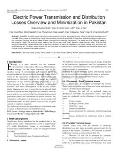
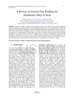
8 Iph (t) = Iph . (1 + TIPH1. (T-Tmeas)) (2). The parameters of a single solar cell Where : TIPH1 is the first temperature coefficient for Iph ; Tmeas is the parameter extraction temperature. Parameter Value Short-circuit current [A] Isc = 3. MODEL OF PHOTOVOLTAIC ARRAY Open-circuit current [V] Voc = Model for plotting the characteristics of PV mod- Quality factor N = ule. series resistance [ ] Rs = 0. In the model (Figure 1) represents a PV cell array connected to First order temperature coefficient for Iph [1/K] TIPH1 = 0. a variable resistor. This resistor has an input ramp which just Temperature exponent for Is TXIS1 = 3.
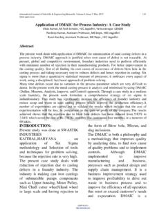
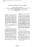
9 Varies resistance linearly in closed circuit until it reaches the Temperature exponent for Rs TRS1 = 0. 30th steps. Inside the array subsystem are 8 rows of photovol- Parameter extraction temperature [ C] Tmeas = 25. taic solar cells connected in series , formed by 8 solar cells of Fixed circuit temperature [ C] TFIXED. SimElectronics library (Fig. 2). This structure can be built in =25. IJSER. any configurations by connecting multiple strings of solar cells in series or in parallel [3,8]. In Fig. 3 are shown the current, voltage and power which are obtained at output of PV array. These are the curves of current, voltage and power versus time.
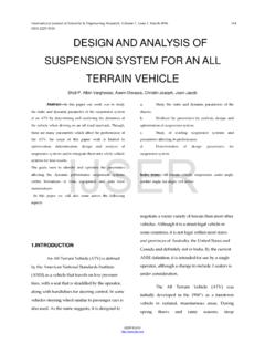
10 When the resistance varies, the current and voltage vary depending on the voltage-time rela- tionship which gives the power curve Fig. 1. The Simulink model for photovoltaic arrays. Fig. 2. Connection of solar cells in PV panel subsystem. The advantage of using of this high level of implementation is to create a simple equivalent circuit, which have much more Fig. 3. Current, voltage and power curves for PV array. IJSER 2016. International Journal of Scientific & Engineering Research , Volume 7, Issue 3, March-2016. ISSN 2229-5518 553. PV Array VI Curves-data The characteristics of V-I and V-P of the photovoltaic array is Irradiance effect on PV Array Performance T=25 oC.