Transcription of Fire Bulletin 3 - 1 and 1 (1/2) Hour Fire Rated MBMA Roof ...
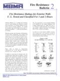
1 Fire ResistanceBulletinMetal Building Manufacturers and 1 Hour Fire RatedMBMA Roof SystemsThe Metal Building Manufacturers Association(MBMA) fire testing activities at UnderwritersLaboratories, Inc. has resulted in listing intheir Fire Resistance Directory three MBMA roofsystems, Design No. P516 which utilizes agypsum wallboard suspended ceiling and No. P265 and P268 which use an acousti-cal tile lay-in suspended ceiling. Design No. P516 provides not only a 1-hourfire resistance rating for the roof assembly but 1-hour protection for structural members locatedabove the ceiling.
2 Designs No. P265 and P268utilize acoustical tile ceiling systems to provide a1- and 1 hour roof/ceiling assembly fire resist-ance rating and also provides 1- and 1 - hour pro-tection to steel members above the ceiling. In addi-tion, the acoustical tile ceilings may have light fix-ture penetrations and duct outlets in the ceiling MBMA building with a fire Rated roof assemblyplaces the metal building in a totally new class ofconstruction with the following take advantage of these fire Rated roof systems,one should make a comparison of costs against anon-combustible metal building (standard metalbuilding with no fire resistance ratings)
3 , or a sprin-klered metal building, or against a ConstructionClass 4 where one-hour fire resistive walls are usedwith a non-fire Rated , noncombustible roof. Ratesmust be developed to see if the return on the addi-tional investment would be most important avenue gained by having a 1-or 1 - hour fire resistive roof assembly is toexpand the market for metal buildings for thoseoccupancies where codes* require Type IB or TypeII construction. This also permits larger area metalbuildings under the code for those occupanciesrequiring fire Rated noncombustible construction details for the listed MBMA roof assemblies are as follows.
4 *The building owner s design professional must determine andspecify applicable load the metal building to be used in areaspreviously restricted, such as gymnasiums,auditoriums, skating rinks, or high occupan-cy the metal building in Type IB or TypeII Fire Resistive Type Construction in thethree model building codes (BOCA, ICBO, and SBCCI) if the one- and two-hour fire Rated walls, columns, and floorsare used in conjunction with the 1- or 1 hour the insurance rate fromConstruction Class 3 to Construction Class5 reducing the rates by as much as 40 per-cent, as shown in MBMA InsuranceBulletin # : This Bulletin was previously released as Insurance Bulletin #17 Metal Building Manufacturers No.
5 P516 Unrestrained Assembly Ratings - 1 Beam Rating - 1 Roof Deck Panels*- No. 26 MSG or painted steel. Panels continuousover two or more spans. End laps to occur overpurlins with panels overlapped a min. of 4 in. Aline of sealant or tape sealant may be used atpanel side and end laps. See Roofing Materialsand Systems Directory Metal Roof DeckPanels (TJPV) category for names of Fasteners - As specified in the respec-tive Classified Roof Deck ConstructionNumber for the Metal Roof Deck and Blankets* - Any faced glass fiberbatt material or mineral wool insulation bearingthe UL Classification Marking.
6 See Batts andBlankets* (BZJZ) Category in Fire ResistanceDirectory or Batts and Blankets* (BKNV) inBuilding Materials Directory for list ofClassified Roof Purlins - C or Z-shaped, min. 8 , weighing min. lb. per lineal ft. madefrom min. No. 16 MSG galvanized or paintedsteel. Spaced max. 60 in. Purlins may bestiffened at the supports if required per structur-al - Steel I beam sections designed as struc-tural supports to the roof purlins. Min. weight ofsteel I beam is lb. per lineal Wire - No. 12 SWG or heavier galva-nized steel wire; twist-tied to steel roof purlinsor joists.
7 Hanger wire attachment spaced notover 60 in. along cold-rolled channel, andlocated at ends of the cold-rolled channels atwalls. When alternate Steel FramingMembers* (Item 8A or 8B) are used, hangerwires are spaced 48 in. (at every thirdmain runner/cross tee intersection). Hangerwires also located adjacent to each main runnersplice location. Cold-Rolled Channel -Min. No. 16 MSG gal-vanized or painted steel channels, 1 in. deepwith 9/16 in. Channel - No. 25 MSG galvanizedsteel, 2 5/8 in. wide, 7/8 in. deep,spaced 24 in. perpendicular to cold-rolledchannels: secured to each cold-rolled channelwith double strand of No.
8 18 SWG galvanizedsteel wire. As an alternate to the furring chan-nels, Steel Framing Members* (Item 8A or 8B)may be Framing Members - (Not Shown) - Asan alternate to Item 8. Main runners nom. 12 , spaced 48 in. cross tees, measuring1 in. across the flange and nom. 4 ft. long,installed perpendicular to main runners andspaced 16 in. Additional cross teesrequired 4 in. from and on each side of wall-board end Framing Members -(Not Shown) - Asan alternate to Items 8 and 8A. Main runnersnom. 12 ft. long, spaced 48 in. Crosschannels, nom. 4 ft.
9 Long installed perpendicu-lar to the main runners, spaced 16 in. cross channels required 4 in. fromand at each side of wallboard and Interiors, Inc. Type RX main runnerand cross DXLG cross World Industries, Inc. - Type DFR-8000*Bearing UL Classification MarkingMetal Building Manufacturers No. P265 Restrained Assembly Rating - 1 or 1 Hr. See Item 3 Unrestrained Assembly Rating - 1 or 1 Hr. See Item 3 Unrestrained Beam Rating 1 Gypsum* - Any 5/8 in. thick gyp-sum wallboard bearing the UL ClassificationMarking as to Fire Resistance. Two layers of5/8 in.
10 Thick by 48 in. wide sheets installed withlong dimension perpendicular to the furringchannels. Inner layer attached to furring chan-nels using 1 in. long Type S bugle head steelscrews spaced 8 in. along butted endjoints and 12 in. in the field of the end joints to occur midway betweencontinuous furring channels and to be backedby joint backer channel which is centered onthe end joints and extends 6 in. beyond bothends of the end joint. Butted end joints to beoffset a min. of 24 in. in adjacent layer attached to the furring channelsthrough inner layer using 1 7/8 in.