Transcription of Design Guide for 3D Printing with Composites - Markforged
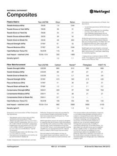
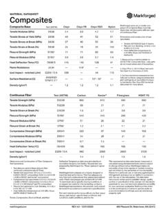
1 Design Guidefor 3D Printing with CompositesForces keyImportant termsYXZXY planeTable of Contents1 Quick Reference Sheet ..01 Plastic ..01 Fiber ..032 Identifying 3D Printing Opportunities ..04 Calculate ROI ..04 Determine material needs and behaviors ..04 When should you print with continuous fiber?..043 What to Consider When Printing ..054 Strategic 3D Printing Design Practices ..07 Use unit tests to validate geometries and save print time ..08 Tolerancing and clearances ..085 Understanding Matrix Materials ..09 Types of matrix materials ..09 Designing for Onyx FR ..096 Diving Deep into Fiber Reinforcement ..10 Types of fiber ..10 Types of fiber fill ..10A brief Composites fiber lesson ..11 How to think about reinforcing with continuous fibers ..12 Basic reinforcement strategy: Shelling ..13 Specialized reinforcement strategies.
2 14 Composites Design GUIDEAt several points in this Guide we discuss different loading conditions with respect to print orientation. Due to the anisotropic nature of 3D printed parts, properties about or along the Z axis of Printing normal to the print bed are different than those of the X and Y axes parallel to the print bed. Properties and behaviors in this Guide are framed in the context of the Z axis or the XY plane. Imporant terms from Eiger, the Markforged 3D Printing software, will be highlighted in BOLD CAPITAL Design GUIDE1version part size Desktop SeriesX: 320 mm ( )Y: 132 mm ( )Z : 154 mm ( )Industrial SeriesX: 330mm ( )Y1: 270 mm ( ) Y2: 250 mm ( ) with fiberZ : 200 mm ( )These build volumes reference the maximum bounding box your part must fit in to print on either a Desktop or Industrial Series Markforged composite printer.
3 Industrial Series printers have a deeper print area when Printing with only guides serve as recommendations and may not reflect all implementations, as 3D Printing is a geometry-dependent process. Unless otherwise specified, data is based on parts printed on Markforged composite printers at 100 micron layer height in Onyx with default print part dimensionsX: mm ( )Y: mm ( ) Z: mm ( )Minimum part size is limited to the extrusion width and height of each bead. The dimensions are derived from the minimum number of roof layers, floor layers, and shells needed to print a part successfully. Minimum unsupported overhang angle : 40oThis is the minimum angle to the horizontal at which a feature of a part can print without needing supports to hold it up. Eiger will generate supports for angles below 45o, but may not be needed in all Reference SheetPlasticMinimum hole diameterXY: mm ( )Z: mm ( )Holes with too small a diameter may close off during Printing or print inaccurately.
4 Horizontal surface holes (Z) print more precisely than vertical surface holes (XY).ZYX XYZZXYZXY1Y2 Composites Design GUIDE2version Reference SheetMinimum engraved feature sizeZ Layer featuresH: mm ( )W: mm ( )Horizontal XY featuresD: mm ( )H: mm ( )Vertical XY featuresD: mm ( )W: mm ( )An engraved feature is one that is recessed below the surface of the model. Common examples include lettering and texture. Engraved features may blend into the rest of the model if they are too small. Minimum post diameterXY: mm ( )Z: mm ( )Posts with too small a diameter may not print precisely. Consider adding dowels or pins to your part for strong vertical posts to avoid shear along layer embossed feature sizeZ Layer featuresH: mm ( )W: mm ( )Horizontal XY featuresD: mm ( )H: mm ( )Vertical XY featuresD: mm ( )W: mm ( )An embossed feature is one that is raised above the surface of the model.
5 Common examples include lettering and texture. Embossed features may blend into the rest of the model if they are too note: To prevent gaps on features less than than 2 mm ( ) wide, Design embosses to be even multiples of mm ( ), the width of a single extrusion of note: Avoid Printing posts with heights (H) more than five times their diameter (D). Tall posts are more susceptible to shear on layer lines. If you do print posts, fillet interfacing edges to reduce stress > 5DH = 5DH < mm( )XYZHWHDWDWHHDWDCOMPOSITES Design GUIDE3version Reference SheetMinimum fiber lengthL: 45 mm ( )The smallest area you can reinforce with fiber is limited to the smallest strand of fiber that can be laid down and cut. This minimum strand length (L) can materialize in a few ways but must also meet the reinforcement width criteria.
6 Smallest reinforced holesSmallest reinforced postPost Diameter: mm ( )It is possible to reinforce vertical posts down to mm ( ) in diameter. However, vertical printed posts may shear along layer lines, so consider integrating dowels, rods, or pins into your part for strong reinforced areaArea: 90 mm2 ( in2)Independent of part shape, the smallest reinforceable area is about 90 mm (but may vary based on specific geometry). The part must also meet the minimum width requirements listed fiber reinforcement part heightFiberglass, HSHT, Kevlar Carbon FiberH: mm ( ) H: mm ( )Four roof and four floor layers of plastic are needed above and below Fiber Groups, meaning the minimum reinforceable height (H) is nine layers thick, leaving one layer for fiber. This value changes with fiber selection since some fibers print at different layer fiber reinforcement feature widthOpen feature Looped featureW: mm ( ) W: mm ( )Thin reinforced features must allow the fiber to double back and meet the endpoint of the fiber with its start.
7 While the minimum width (Wopen ) of an open feature on a part must fit two fiber strands, the minimum reinforcement width (Wlooped ) can be thinner if the segment in question allows the fiber to form a holes are too small to reinforce with a given number of concentric fiber rings because of the minimum fiber length. In these cases, you can simply increase the number of CONCENTRIC FIBER RINGS. Here are the minimum hole sizes for 1-3 rings of rings D3: mm ( )Two ringsD2: mm ( )One ringD1: mm ( )WopenWloopedHAD1D2D3 DCOMPOSITES Design GUIDE4version 3D Printing OpportunitiesWhen should you print with continuous fiber?Continuous Fiber Fabrication (CFF) serves as the backbone for strong 3D printed parts. Inlaid fibers within a printed plastic matrix form a composite part in which the properties of the fiber provide high stiffness, toughness, strength, or heat strengthThe strength of a fiber reinforced part comes from the combined strength of the plastic and the continuous fiber strands woven throughout the part.
8 This can make parts comparable to aluminum in strength and fibers can vastly increase the lifetime of a part. Fibers strengthen the part far beyond traditional plastics, meaning a reinforced part can hold up much better over an extended period of time than a standard plastic part. Optimized propertiesContinuous Fiber Fabrication is unique in that you can selectively reinforce a part for its use-case. Tailor a part s strength profile exactly for its application by adding continuous fibers where strength is needed printers vary widely in size, material, and method simply put, they are just tools to help you create specific parts. Just as you wouldn t use a screwdriver on a nail, a 3D printer is well-suited for certain types of parts and ineffective for others. The key to determining whether to 3D print a part stems from its material properties and return on investment (ROI).
9 Calculate ROIUse ROI calculations to justify which parts or subassemblies will benefit from 3D Printing . Upload your parts to Markforged s Eiger software to get the material cost and print time, and compare this to estimates from other manufacturing platforms. This should give you a sense for the time and cost savings involved in creating your considerationsTurn to 3D Printing when the costs of traditional manufacturing are prohibitively expensive for your needs. 3D Printing is often appropriate for low- to mid-volume applications, but for a given part there is always an inflection point at which other manufacturing methods become more cost-effective. Compare cost-per-quantity values to discover this tipping analysis3D Printing allows for rapid iteration so you can test out many different designs early and often to refine your models.
10 Continuous fiber reinforcement facilitates strong parts for works-like prototypes and end-use that you can improve print-by-print and implement in a matter of days. Look for opportunities to cut down on lengthy lead times with additive material needs and behaviorsConsider the material requirements of your part. How strong or stiff does it need to be? What environment will your part be in? How many cycles does it need to last? How much can it weigh?Use these considerations to select a material that suits the Quantity3D PrintingTraditional ManufacturingCost per partMachining3DP3DP3 DPDay 1 Day 4 Composites Design GUIDE5version to Consider When PrintingAs you Design your part, consider how it can be optimized for the layer-by-layer Printing process. Below are six considerations to keep in mind when designing your parts:5.