Transcription of Temperature head transmitter - Endress
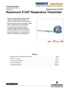
1 Technical informationTI 078R/09/enNr. 51002073 Temperature head transmitteriTEMP HART TMT 182 Universal head transmitter for resistance thermometers (RTD), thermocouples (TC), resistance and voltage transmitters (mV), settable via HART -protocol, for installation in a sensor head Form BApplication Temperature head transmitter with HART -protocol for converting various input signals into an scalable4 to 20 mA analogue output signal Input:Resistance thermometer (RTD)Thermocouple (TC)Resistance transmitter ( )Voltage transmitter (mV) HART -protocol for front end unit or panel unit operation using the hand operating module (DXR 275) or PC (e. g. ReadWin 2000, COMMUWIN II or FieldCare)Your benefits Universal settings with HART -protocol for various input signals Operation, visualisation and maintenance via PC, e.
2 G. COMMUWIN II operating software 2 wire technology, 4 to 20 mA analogue output High accuracy in total ambient Temperature range Fault signal on sensor break or short circuit, presettable to NAMUR NE 43 EMC to NAMUR NE 21, CE UL recognized component to UL 3111-1 GL Germanischer Lloyd marine approval Ex-Certification- ATEX Ex ia and dust zone 22 incompliance with EN 50281-1- FM IS- CSA IS Galvanic isolation Output simulation process value indicator function Customer specific linearization Linearization curve match Customer specific measurement range settings or expanded SETUP(see Questionnaire, Page 7)TMT 1822 Endress +HauserFunction and system designMeasuring principleElectronic measurement and conversion of input signals in industrial Temperature systemThe iTEMP HART TMT 182 Temperature head transmitter is a two wire transmitter with ananalogue output.
3 It has measurement input for resistance thermometers (RTD) in 2-, 3- or 4-wire connection, thermocouples and voltage transmitters. Setting up of the TMT 182 is done using the HART -Protocol with hand operating module (DXR 275) or PC (COMMUWIN II).InputMeasured variableTemperature ( Temperature linear transmission behaviour), resistance and voltageMeasuring rangeThe transmitter records different measuring ranges depending on the sensor connection and input of inputResistance thermometer (RTD)TypeMeasurement rangesmin. meas. rangePt100Pt500Pt1000acc. to IEC 751-200 to 850 C (-328 to1562 F)-200 to 250 C (-328 to 482 F)-200 to 250 C (-238 to 482 F)10 K10 K10 KNi100Ni500Ni1000acc. to DIN 43760-60 to 250 C (-76 to 482 F)-60 to 150 C (-76 to 302 F)-60 to 150 C (-76 to 302 F)10 K10 K10 K Connection type: 2-, 3- or 4-wire connection Software compensation of cable resistance possible in the 2 wire system(0 to 30 ) Sensor cable resistance max.
4 20 per cable in the 3 and 4 wire system Sensor current: mAResistance transmitterResistance 10 to 400 10 to 2000 10 100 Thermocouple (TC)B (PtRh30-PtRh6)C (W5Re-W26Re)1D (W3Re-W25Re)1E (NiCr-CuNi)J (Fe-CuNi)K (NiCr-Ni)L (Fe-CuNi)2N (NiCrSi-NiSi)R (PtRh13-Pt)S (PtRh10-Pt)T (Cu-CuNi)U (Cu-CuNi)2acc. to IEC 584 Part 11) acc. to ASTM E9882) acc. to DIN 437100 to +1820 C (32 to 3308 F)0 to +2320 C (32 to 4208 F)0 to +2495 C (32 to 4523 F)-270 to +1000 C (-454 to 1832 F)-210 to +1200 C (-346 to 2192 F)-270 to +1372 C (-454 to 2501 F)-200 to +900 C (-328 to 1652 F)-270 to +1300 C (-454 to 2372 F)-50 to +1768 C (-58 to 3214 F)-50 to +1768 C (-58 to 3214 F)-270 to +400 C (-454 to 752 F)-200 to +600 C (-328 to 1112 F)500 K500 K500 K 50 K 50 K 50 K 50 K 50 K500 K500 K50 K50 K Cold junction: internal (Pt100) Cold junction accuracy.
5 1 KVoltage transmitters (mV)Millivolt transmitter (mV)-10 to 75 mV5 mVTMT 182 Endress +Hauser3 OutputOutput signalAnalogue 4 to 20 mA, 20 to 4 mASignal on alarm UnderrangingLinear drop to mA Overranging:Linear rise to mA Sensor break; sensor short-circuit (not for thermocouples TC): mA or mALoadmax. (VPower supply - V) / A (Current output)Linearisation/transmission behaviourTemperature linear, resistance linear, voltage linearFilter1st order digital filter: 0 to 100 sGalvanic isolationU = 2 kV AC (input/output)Input current required mACurrent limit 23 mASwitch on delay4 s (during power up Ia = mA)Power supplyElectrical connectionHead transmitter terminal connectionsSupply voltageUb = to 35 V, polarity protectedResidual rippleAllowable ripple Uss 3 V at Ub 13 V, fmax.
6 = 1 kHzTMT 1824 Endress +HauserPerformance characteristicsResponse time1 sReference operating conditionsCalibration Temperature : +23 C ( F) 5 KMaximum measured errorInfluence of supply voltage deviation from 24 V Percentages refer to the full scale of ambient Temperature ( Temperature drift) Resistance thermometer (RTD):Td= (15 ppm/K * max. meas. range + 50 ppm/K * preset meas. range) * Resistance thermometer Pt100:Td= (15 ppm/K * (range end value + 200) + 50 ppm/K * preset meas. range) * Thermocouple (TC):Td= (50 ppm/K * max. meas. range + 50 ppm/K * preset meas. range) * = Deviation of the ambient Temperature according to the reference condition (+23 C ( F) 5 K).Influence of load Values refer to the full scale valueLong-term stability 0,1 K/year or under reference operating conditions.
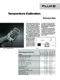
7 % refer to the set span. The highest value is of cold junctionPt100 DIN IEC 751 Cl. B (internal cold junction with thermocouples TC)Installation conditionsInstallation instructions Installation angle:no limit Installation area:Connection head accord. to DIN 43 729 Form B; TAF 10 field housingTypeMeasurement accuracy1 Resistance thermometer RTDPt100, Ni100Pt500, Ni500Pt1000, K or K or K or TCK, J, T, E, L, UN, C, DS, B, Rtyp. K or K or K or rangeMeasurement accuracy11) % is related to the adjusted measurement range. The value to be applied is the transmitter ( )10 to 400 10 to 2000 or or transmitters (mV)-10 to 75 mV 20 V or 182 Endress +Hauser5 Environment conditionsAmbient Temperature limits-40 to +85 C (-40 to 185 F) for Ex-area, see Ex-certificateStorage Temperature -40 to +100 C (-40 to 212 F)Climate classas per EN 60 654-1, class CCondensationallowableDegree of protectionIP 00, IP 66 installedShock and vibration resistance4g / 2 to 150 Hz as per IEC 60 068-2-6 Electromagnetic compatibility (EMC)Shock resistance and interference emission as per EN 61 326-1 (IEC 1326) and NAMUR NE 21 Mechanical constructionDesign, dimensionsDimensions of the head transmitter in mm (inches)Weightapprox.
8 40 gMaterial Housing:PC Potting:PURT erminalsCable up to max. mm2 (secure screws)Human interfaceDisplay elementsNo display elements are present directly on the Temperature measured value display can be called up using the ReadWin 2000, COMMUWIN II or FieldCare PC elementsNo operating elements are present directly on the display. The Temperature transmitter is configured via remote operation with the ReadWin 2000 PC 1826 Endress +HauserRemote operationConfigurationHand operating module DXR 275 or PC with Commubox FXA 191 and operating software(ReadWin 2000, COMMUWIN II or FieldCare).InterfacePC interface RS232 and Commubox FXA parametersSensor type and connection type, engineering units ( C/ F), measurement range, internal/external cold junction, compensation of wire resistance with 2-wire connection, failure mode, output signal (4 to 20/20 to 4 mA), digital filter (damping), offset, TAG + descriptor (8 + 16 characters), output simulation, customer specific linearization, process value indicator functionCertificates and approvalsCE-MarkThe measurement system fulfils the requirements demanded by the EU regulations.
9 Endress +Hauser acknowledges successful unit testing by adding the CE approvalFor further details on the available Ex versions (ATEX, CSA, FM, etc.), please contact your nearest E+H sales organisation. All relevant data for hazardous areas can be found in separate Ex documentation. If required, please request copies from us or your E+H sales standards and guidelines EN 60529:Degrees of protection by housing (IP-Code) EN 61010:Safety requirements for electrical measurement, control and laboratory instrumentation. EN 61326 (IEC 1326):Electromagnetic compatibility (EMC requirements) NAMURS tandardization association for measurement and control in chemical and pharmaceutical 182 Endress +Hauser7 Ordering informationStandard setup / StandardeinstellungSensorTC( ) B( ) C( ) D( ) E( ) J()K ()L ()N ()R ()S()T ()URTD( ) Pt100( ) Pt500( ) Pt1000( ) Ni100( ) Ni500( ) Ni1000( ) 2 wire( ) 3 wire( ) 4 wireUnit / Einheit() C() FRange / MessbereichLow scale(not / nicht PROFIBUS-PA)AnfangBitte beachten!
10 :Messbereich und min. Spanne(s. Techn. Daten)High scaleEndeNote!:Range and min. span(s. Techn. data)Bus address / Busadresse[ ](only / nur PROFIBUS-PA)Expanded setup / Erweiterte EinstellungReference junction /( ) intern( ) extern(only / nur TC)Vergleichsstelle[ C; F]Compensation wire resistance /[ Ohm][ Ohm](only / nur RTD 2 wire)(only / nur HART, PA RTD 2 wire)Kompensation LeitungswiderstandFailure mode /( )<3,6 mA()>21,0 mA(not / nicht PROFIBUS-PA)FehlerverhaltenOutput / Ausgang( ) mA( ) mA(not / nicht PROFIBUS-PA)Damping / D mpfung[0, 1, 2,.., 8s]Offset[-9, +9,9K]TAGPCPHART(HART: 8 char. TAG + 16 char. Descriptor , PROFIBUS-PA: 32 char.)PROFIBUS-PAQuestionnaire Endress +Hauser iTEMP Temperature transmitterCustomer specific setup / Kundenspezifische Einstellung,,,(only / nur PCP)[0, 1, 2.]