Transcription of BLACKMER LB COMPRESSORS
1 BLACKMER LB COMPRESSORS 960474 INSTRUCTIONS NO. 588/A Installation, Operation, and Maintenance Instructions Section Effective Replaces 502 Nov 2004 July 2004 MODELS: LB161B, LB361B, LB601B LB162B, LB362C, LB602B TABLE OF CONTENTS SAFETY 1 GENERAL INFORMATION compressor Data .. 2 Nameplate Data .. 3 Maximizing compressor 4 INSTALLATION Location and 5 Mounting the compressor Unit .. 5 Stationary 5 Truck Mounted COMPRESSORS .. 5 compressor 6 V-Belt 6 PTO Drive .. 6 Liquefied Gas Transfer Piping Schematic.
2 7 Typical Transfer compressor , Drawing .. 7 Relief 8 4-Way Valves .. 8 Liquid 8 Temperature and Pressure Switches .. 8 & 9 Pressure Gauges .. 9 OPERATION Pre-Start up Check List .. 9 Start Up Procedure .. 10 MAINTENANCE Service Schedule .. 11 Tool 11 Bolt Torque Table .. 12 Crankcase Lubrication .. 12 Setting the Oil 12 compressor 13 compressor 14 VALVE 16 SEAL (PACKING) 18 BEARING 19 OIL PUMP 20 EXTENDED 21 SAFETY DATA This is a SAFETY ALERT SYMBOL.
3 When you see this symbol on the product, or in the manual, look for one of the following signal words and be alert to the potential for personal injury or property damage. Warns of hazards that WILL cause serious personal injury, death or major property damage. Warns of hazards that CAN cause serious personal injury, death or major property damage. Warns of hazards that CAN cause personal injury, or property damage. NOTICE Indicates special instructions which are very important and must be followed. NOTICE BLACKMER COMPRESSORS MUST only be installed in systems which have been designed by qualified engineering personnel.
4 The system MUST conform to all applicable local and national regulations and safety standards. These instructions are intended to assist in the installation and operation of BLACKMER COMPRESSORS and MUST be kept with the compressor . BLACKMER compressor service and maintenance shall be performed by qualified technicians ONLY. Service and maintenance shall conform to all applicable local and national regulations and safety standards. Thoroughly review this manual, all instructions and hazard warnings, BEFORE performing any work on the compressor .
5 Maintain ALL system and compressor operation and hazard warning decals. For handling liquefied gas, NFPA Pamphlet 58 should be consulted. SAFETY DATA 588/A page 2/24 Flammable gas can cause death, serious personal injury or property damage FLAMMABLE GAS AND/OR LIQUID CAN FORM EXPLOSIVE MIXTURES WITH AIR CAUSING PROPERTY DAMAGE, SERIOUS PERSONAL INJURY OR DEATH Hazardous pressure can cause serious personal injury or property damage FAILURE TO RELIEVE SYSTEM PRESSURE PRIOR TO PERFORMING compressor SERVICE OR MAINTENANCE CAN CAUSE SERIOUS PERSONAL INJURY OR PROPERTY DAMAGE.
6 Hazardous machinery can cause serious personal injury. FAILURE TO DISCONNNECT AND LOCKOUT ELECTRICAL POWER OR ENGINE DRIVE BEFORE ATTEMPTING MAINTENANCE CAN CAUSE SEVERE PERSONAL INJURY OR DEATH Hazardous voltage. Can shock, burn or cause death. FAILURE TO DISCONNNECT AND LOCKOUT ELECTRICAL POWER BEFORE ATTEMPTING MAINTENANCE CAN CAUSE SHOCK, BURNS OR DEATH Hazardous or toxic fluids can cause serious injury. IF HANDLING HAZARDOUS OR TOXIC FLUIDS, SYSTEM MUST BE FLUSHED AND DECONTAMINATED, INSIDE AND OUT, PRIOR TO PERFORMING SERVICE OR MAINTENANCE Hazardous pressure can cause serious personal injury or property damage DISCONNECTING FLUID OR PRESSURE CONTAINMENT COMPONENTS DURING compressor OPERATION CAN CAUSE SERIOUS PERSONAL INJURY, DEATH OR MAJOR PROPERTY DAMAGE Hazardous gases can cause property damage, personal injury or death EXPLOSIVE GAS CAN CAUSE PROPERTY DAMAGE, PERSONAL INJURY, OR DEATH.
7 Extreme Heat can cause personal injury or property damage EXTREME HEAT CAN CAUSE PERSONAL INJURY OR PROPERTY DAMAGE GENERAL INFORMATION compressor Data The models listed are single-stage, vertical, air-cooled reciprocating style COMPRESSORS with single acting cylinders. Single-Seal Models Double-Seal Models LB161B LB162B LB361B LB362C LB601B LB602B Minimum / Maximum RPM * 350 / 825 350 / 825 350 / 790 Reduce maximum speeds by 9% for continuous duty operation.
8 Displacement @ min rpm - CFM (m3/hr) @ max rpm - CFM (m3/hr) ( ) ( ) ( ) ( ) ( ) ( ) Max. BHP (kw) 10 ( ) 15 (11) 40 (30) MAWP - psia (kPa) 350 (2,413) Maximum Discharge Temperature 350 F (176 C) Rotation Direction Bi-Directional Table 1 - compressor Data GENERAL INFORMATION 588/A page 3/24 MODEL: LB ID#: SERIAL NO: Before proceeding: 1. Note the nameplate data in the space provided above. 2. Obtain the appropriate parts lists for the model in question. Manuals and Parts Lists for BLACKMER products may be obtained from BLACKMER 's website ( ) or be contacting BLACKMER 's Customer Service.
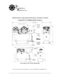
9 NAMEPLATE DATA A nameplate is attached to the side of all BLACKMER COMPRESSORS showing the Model No., No., and Serial No. These numbers should be available when information or parts are needed for a particular unit. The basic size and type of the compressor is indicated by "Model No." A suffix letter is used on most models to indicate the version. Figure 2 - compressor Nameplate Figure 1 - Typical compressor GENERAL INFORMATION 588/A page 4/24 An 11 character " No." identifies the construction of the compressor . B A B A C 1 T A 4 A A VALVES Code Fields Steel.
10 W/ Liquid Relief BA 1 & 2 O-RINGS Field 3 Buna-N B GASKETS Field 4 Aluminum A PISTON RINGS Field 5 Carbon Filled PTFE C SEAL (PACKING) ORIENTATION Field 6 All Lips up 1 SEAL MATERIAL Field 7 PTFE T CYLINDER & HEAD Field 8 Ductile Iron A Ductile Iron D