Transcription of Astral Milenium Sand Filter Installation Instructions ...
1 Milenium sand Filter SystemInstallation Instructions Introduction:INSIDE:Setting Up your The system To Your Your The Pump The Filter ..12 Winterizing Your Filter system Parts s Warns about hazard that CAN cause serious personal injury andproperty damage if ignored.(For cord and plug connected units.) Do not bury cord. Locatecord to minimize abuse from lawn mowers, hedge trimmers andother lawn equipment.(For cord and plug connected units) To reduce the risk of electricshock, replace damaged cord immediately.(For cord and plug connected units) Risk of electric only to a grounding type receptacle protected by aground-fault circuit interrupter (GFCI).
2 Contact a qualifiedelectrician if you cannot verify that the receptacle if protected bya GFCI.(For cord and plug connected units) To reduce the risk of electricshock, do not use an extension cord to connect unit to electricsupply; provide a properly located to information on motor nameplate for electricalservice data. If the pump on your system is suppliedwith a 3-prong twist lock 115V plug, then the appro-priate male receptacle should be installed. For systemswith a standard 3-prong 115V plug, we recommend agrounded receptacle be installed with a built-in GroundFault Circuit Interrupter (GFCI). Motors should havefused disconnect switch or circuit breaker and wiresize large enough for pump horsepower and distancefrom power source.
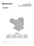
3 Wiring should be done in accor-dance with applicable codes by a competent Data3-prong twist-lock plug Standard 3-prong plugWhat you should have:Contents of carton:CodeDescriptionCodeDescriptionA24 181-0100 Filter body522503-0050 Pressure gauge setB720R1750057 O-ring 170x5, 75600555R0401 Tee adapterC24182-1003 Plastic V-clamp set7074065008A Air releif plugE22358 Selector valve / Multiport800470R0319N GasketF24182-0007 Flange 24mm924181-0004 Water drain setJ22503-0017 Filter collector / Standpipe1024181-0006 GasketK00638 Collector arm / Lateral1115780-0602 Water drain plugM19460R0001 Monobloc baseN24457-1130 Pump Setting up your system :4 Step 1 Remove Filter , pump and base from the (2) 1/4 x 20 bolts and washers, mount pumpto base.
4 The pump mounts using the jack nutsinstalled in the base. The pump should be posi-tioned such that the pump strainer is supported bythe system base. Note: Some systems are supplied with push-ingrommet nuts for the pump mount. Install thesegrommets in the base using the pre-drilled holesnoted. (See Step 1A).Step 1 APush the grommet nuts into the pre-drilled holes inthe system base. Use the illustration at the right toensure the correct holes are used. Position theslots in the pump motor base over the grommetnuts and install the self-tapping screws to securethe pump to the fi lter, pump and base from the carton. Using (2) bolts and washers, mount pumpto base.
5 The pump should be positionedsuch that the pump strainer is supported bythe system VALVE Installation : Carefully remove all sandparticles from the mounting location, being especiallycareful of the bolt holes and O-ring groove. Position the O-ring in the groove. Place valve on tank and rotate until thevalve inlet (marked PUMP ) is approximately in line withthe pump outlet opening. Install the hex-head bolts andtighten uniformly, being careful not to pressure gauge, after wrapping brass threads with4 wraps of teflon tape. NOTE: Seven position valves are equipped with a sightglass which must be HANDTIGHT only. Sith t fltf t 150 Lbs.
6 Of sand . Be sure the standpipe assembly remains centered while pouring the sand . Now remove the standpipe cover and place the diverter on top of the fi lter VALVE Installation : Carefully remove all sand particles from the mounting location, being especially careful of the O-ring groove. Position the O-ring around the bottom of the multiport. Place valve on tank and rotate until the valve inlet (marked PUMP ) is approximately in line with the pump outlet opening. Install the V-clamp set to connect the multiport to the fi lter body. Install pressure gauge, after wrapping brass threads with 4 wraps of tefl on tape. NOTE: Selector Valve is equipped with a sight glass which must be HANDTIGHT only.
7 Some pressure gauges come with tefl on tape factory installed. Setting up your system :5 Setting up your system :Connect the pre-assembled plumbing connectionfrom the pump discharge to the valve inlet usingthe union nuts on either end of the flexible : Ensure the o-rings are in theadapter groove at each end of the hose. These o-rings were shipped installed at the factory andcould dislodge during transit. The adapter o-rings may be supplied in thesystem hardware 4-way valve: Install threaded adapter into thepump discharge, tighten handtight plus 1/2 install the other adapter into the dial valveinlet, tighten in the same manner.
8 Place one hoseclamp over each end of the pump to Filter hose,push hose onto each adapter. Position the clampover barbed section of the adapter and tightenwith screw driver until your system is supplied with a backwash adapter:Remove threaded adapter and tape from the hardwarekit. Prepare backwash fittings by wrapping threadswith teflon tape in a clockwise rotation, four to eightwraps is usually sufficient. Install adapter into thewaste port of the are now ready to connect the system to your pool (see page 7)kit. Prepare backwash fi ttings by wrapping threads with tefl on tape in a clockwise rotation, four to eight wraps is usually suffi cient.
9 Install adapter into the waste port of the fi pre-assembled plumbing connection by wrapping the threaded end with tefl on tape in a clockwise rotation, four to eight wraps is usually suffi cient. Connect the pre-assembled plumbing connection from the pump discharge to the valve inlet: tighten the threaded adapter end of the fl exible hose into inlet on the multiport labeled pump handtight plus 1/2 turn; then attach the union nut end onto the pump : Ensure the o-ring is in the adapter groove on the pump discharge. This o-ring was shipped installed at the factory and could dislodge during transit. The adapter o-ring may be supplied in the system hardware system -to-pool plumbing connection:7 Install four barbed adapters (B) using tefl on tape in the following lacations:8 system startup:10 Press down on the dial valve handleand rotate to WINTERIZE, releasethe handle.
10 This action will allow airinto the tank and prevent excessiveback-flow through the the pump strainer:Unscrew and remove the clear strainer the pump strainer:Replace the clear strainer (cleaning) the dial valve to water flow in sight glass andwhen clear (usually 2-3 minutes)stop valve to RINSE, run for 20-30seconds. This action removes anydebris trapped in the Filter duringbackwash. (7 position valve only). valve to pump, you have now resumedfiltering your the Filter system :13 Drain the Filter tank by first removing thedrain and then set dial valve to the drain cap once Filter is strainer lid125461-01024 Bacap basket handle124561-02055 Bacap strainer basket124561-02028 Union nut2021939 Drain plugs o-ring1723013002510 Drain Bacap pump housing125461-02033 Strainer lid O-ring 118x4 NBR 50 Sh(A)177A118004013 Bacap pump base125461-05026 Link fl at gasket mm NBR 70 Sh(A)