Transcription of TOOLING ALLOYS DATA SHEET CPM 15 V
1 P A G E 1/ 4 T O O LI N G A L L O Y S | C P M 1 5 V CHEMICAL COMPOSITION Carbon % Chromium % Vanadium % Molybdenum % Manganese % Silicon % CPM 15 V is a newly developed tool steel produced by the special Crucible Particle Metallurgy Process. The material contains approximately 50% more ultra wear resistant vanadium carbide than is contained in CPM 10 V. As a result, the degree of wear resistance has been dramatically increased. The advantage in comparison to conventional steel manufacture is that an absolutely homogeneous microstructure in the powder metallurgical production process is achieved, producing significantly better mechanical properties.
2 CPM 15 V has been developed for applications where the highest demands for wear resistance are imposed, and where tungsten carbides cannot be effectively utilized due to their lower toughness characteristics. TYPICAL APPLICATIONS _ blanking and punching tools (thin sheets) _ tools for the powder pressing industry _ extrusion dies and hole punching tools _ knives for electric SHEET steel _ knives for cutting foil, film and paper _ rotary cutters _ general items subject to wear PHYSICAL PROPERTIES Modulus of elasticity E [kN/mm ] 235 Specific weight [kg/dm ] Coefficient of thermal expansion over temperature range of [mm/mm k]
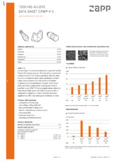
3 21 - 200 C 21 - 450 C 21 - 600 C x 10-6 x 10-6 x 10-6 POWDER METALLURGICAL AND CONVENTIONAL MICROSTRUCTURE The uniform distribution of carbides in the powder-metallurgical structure compared to conventional tool steels with big carbides and carbide clusters. TOUGHNESS Charpy C-Notch impact test 01020304050D262M264 CPMRex M464 CPM10 V63 CPM15 V63 JouleHRc Standard size of the Charpy-test-piece with a mm notch radius. WEAR RESISTANCE Crossed Cylinder wear test 0150300450600750900D262M263 CPMRex M463 CPM10 V64 CPM15 V63 104 MN/mm HRc Reciprocal of wear rate in wear test with non lubricated crossed cylinder in contact with a rotation tungsten carbide cylinder.
4 TOOLING ALLOYS DATA SHEET CPM 15 V ZAPP IS CERTIFIED TO ISO 9001 P A G E 2/4 T O O LI N G A L L O Y S | C P M 1 5 V HEAT TREATMENT ANNEALING SOFT ANNEALING The material is heated slowly and uniformly to a temperature of 870 - 900 C; maintain the temperature for 2 hours and allow to cool slowly to 550 C in the furnace at a cooling rate of 15 C per hour. Final cooling is carried out in still air. The typical hardness achieved by soft annealing is approx. HB 250. STRESS RELIEVING Stress relieving follows rough machining by heating to 600 - 700 C. After complete heat penetration, cooling is carried out in the furnace down to a temperature of approx.
5 500 C. Further cooling is than achieved in still air. HARDENING Hardening of CPM 15 V usually involves the use of 3 preheating stages (at approx. 450 - 500 C/ 850 - 900 C). The material is then heated rapidly from the preheating temperature to the austenitizing temperature in the rage of 1070 - 1180 C in order to attain a corresponding degree of dissolution of the alloy elements. A holding time following complete heat penetration of at least 30 minutes is recommended. QUENCHING Air, hot bath or oil quenching can be used. We recommend hot bath quenching at a temperature of approx. 550 C. If protective gas is used or vacuum heat treatment is carried out, due regard must be paid to ensuring that the reasonable quenching rate is achieved (at least at 5 bar pressure).
6 TEMPERING Immediately temper after the material has cooled down below 40 C. Triple tempering is recommended. It is important to allow the tools to cool to room temperature between the tempering processes. The standard tempering temperature is 540 550 C. To ensure complete tempering, temperatures below 540 C should be avoided. TEMPERING DIAGRAM 505254565860626466540550565595 Hardness HRc1180 C1120 C1070 CTempering temperature C HEAT TREATMENT INSTRUTIONS 1st preheating 450-500 C 2nd preheating 850-900 C Hardening as specified in table Tempering 3 x each 2 hours as specified in table Quenching after hardening in hot bath at approx.
7 550 C or in vacuum at least at 5 bar overpressure. Required hardness HRc 1 Austenit-izing tempe-rature C Holding time at austenit-izing tempe-rature minutes* Tempering tempera-ture[ C] 59 1070 40 550 60 1120 30 550 63 1180 15 550 * Previous preheating at 870 C. The data referred to 13 mm round bar samples. The holding times at austenitizing temperature should be correspondingly adapted for large and very thin profile dimensions. The maximum permissible austenitizing temperature of 1180 C must not be exceeded. P A G E 3/4 T O O LI N G A L L O Y S | C P M 1 5 V MACHINING DATA TURNING Cutting parameter Turning with cemented carbide medium turning finish turning HSS Cutting speed (VC) m/min.
8 80-110 110-150 15-20 Feed (f) mm/U Cutting depth (ap) mm 2 4 Tools according ISO P 10-P 20* P 20* - * Use wear resistant coated cemented carbide, Coromant 4015 or Seco TP 100. MILLING FACE- AND EDGEMILLING - Cutting parameter Milling with cemented carbide medium turning finish turning HSS Cutting speed (VC) m/min. 80-130 130-160 15 Feed (f) mm/U Cutting depth (ap) mm 2-4 1-2 1-2 Tools according ISO K 15* K 15* * Use wear resistant coated cemented carbide, Coromant 4015 or Seco TP 100. END MILLING Solid carbide Milling cutter w. indexable tips Coated HSS Cutting speed (VC) m/min.
9 45-50 90-110 5-8 Feed (f) mm/U ** ** ** Tools according ISO K 20 P 25** - * for TiCN-coated end mills made of HSS VC 25-30 m/min. ** depends on radial depth of cut and on milling cutter - diameter ** Use wear resistant coated cemented carbide, Coromant 3015 or SECO T15M. DRILLING SPIRAL DRILL MADE OF HSS Driller- mm Cutting speed (VC) m/min. Feed (f) mm/U -5 10-12* 5 -10 10-12* 10 -15 10-12* 15 -20 10-12* * for TiCN-coated end mills made of HSS VC 25-30 m/min. CARBIDE METAL DRILLER Cutting parameter Drill type insert drill Solid carbide tip Coolant bore driller with carbide tip* Cutting speed (VC) m/min.
10 120-150 60-80 35 Feed (f) mm/U ** ** ** * driller with coolant bores and a soldered on carbide tip ** depends on driller-diameter GRINDING Grinding method soft annealed hardened Surface grinding, straight grinding wheels A 13 HV B 107 R75 B3* 3SG 46 GVS** A 46 GV Surface grinding A 24 GV 3SG 36 HVS** Cylindrical grinding A 60 JV B126 R75 B3* 3SG 60 KVS** A 60 IV Internal grinding A 46 JV B126 R75 B3* 3SG 80 KVS** A 60 HV Profile grinding A 100 LV B126 R100 B6* 5SG 80 KVS** A 120 JV * for these applications we recommend CBN-wheels ** grinding wheel from the company Norton Co. P A G E 4 / 4 T O O LI N G A L L O Y S | C P M 1 5 V ROUND BAR DIMENSIONS, peeled or turned mm mm mm mm mm mm mm mm mm mm mm mm mm mm mm mm FLAT BAR DIMENSIONS, prefinished in thicknesses mm mm Further dimensions are available on request.