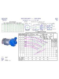
Transcription of BULLETIN 65.000.224 NSN: 4320-00-075-0003 …
1 January 2005 HOME OFFICE Cedarburg, WI 53012 Box 286 262-377-7000 FAX 262-377-7330 SCOTDIVISION OFARDOX December 2003 SCOTINSTALLATION, OPERATION ANDMAINTENANCE MANUAL FORMODEL DCSC 25115A PUMPBULLETIN : 4320-00-075-0003 CONTRACT NO. SP0750-03-M-S795 KEY NO. PART , Retainer Ass , , AssemblyKEY NO. PART Bolt3. Suction port below pumping level provide Plenty of room for inspection and Easy protection from freezing when idle in Correct power supply to motor; all wiring shouldmeet National Electrical and Local Codes and If outdoors, protection from the Suction and discharge gauges are useful tocheck pump operation and are excellent trouble indica-tors. Install gauges in the lines if pump nozzles do nothave gauge taps.
2 Observe these precautions wheninstalling piping:1. Support close to, but independently of Use at least next larger pipe for suction and Keep as straight as possible, with few or no bendsand Remove burrs, sharp edges,ream pipe cuts andmake joints Don t spring pipe to make connections; strainmust not be transmitted to Allow for pipe expansion with hot fluids; expansionjoints are not Size and install suction piping to keep pres-sure loss at minimum and to provide correct NPSH:1. Straight length not less then ten times suction pipediameter should be provided at pump Size must never be smaller than suction port; forlong runs use one or two sizes Pipe should slope upward to pump, even for hori-zontal Use eccentric reducer at pump, eccentric Use 45 or long-sweep 90 Use flapper type foot valve, but only to hold primewhen pump is shut down and suction level is Use grate valves only, for parallel connections andfor isolating pump when shut down.
3 Stem must behorizontal or slope down. Never use globe valves insuction Some close-coupled pumps permit dis-charge port location at any of four positions, 90 by removing cover bolts, rotating casing, andreplace bolts. Be sure there is adequate clearance withselected position between wall or tank, motor conduitbox and for bearing lubrication. Casing may extendbeyond base or pump for shortage and damage immediatelyupon arrival. Note damage or shortage on freight bill(bill of lading); immediately file claim with Pay particular attention to conduit box, exter-nal hardware and accessories. Touch up abrasions orscratches with approved paint. By hand, test that shaftrotates If extensive or serious external damage isnoted, if impeller is damaged (look in ports), or if shaftbinds or sticks, disassemble as required to permit inter-nal with care.
4 Dropping or jarring can seriouslydamage motor bearings or break pump parts. Lift withdevice having capacity for pump weight and use liftinghooks or eye bolts (if provided) or rig double slingaround motor frame and pump casing. Do not use slingthrough pump motor adapter nor around suction anddischarge pump in clean, dry, well-ventilated area, free fromrapid or wide changes in temperature. Suitably cover tokeep chips, debris, dirt and dust from pump. Make sureheavy objects will not drop or fall on pump. For storageof six months or longer:1. Coat exposed, machined surface with rust Consult applicable motor maintenance manual forprocedures to follow if atmospheric conditions Rotate shaft several revolutions at least once eachsix months; once each month if conditions are At the very least, drain moisture from the TEFC motors regularly.
5 Best to use desiccant or eaters tokeep moisture from After long storage, particularly if conditions werepoor, thoroughly clean and dry motor and pumpbefore placing in Pump location should provide the following:1. Install as close to suction supply as Shortest and most direct suction pipe lift must not exceed limit for pump. NPSH available must equal or exceed pump , OPERATION AND MAINTENANCEMODEL DCSC 25115A PUMP1. If discharge line is short, size may be same as dis-charge port; if long, use one or two sizes For long horizontal runs keep grade as even aspossible; avoid high spots and loops. Trapped airwill throttle flow and may result in erratic Install check and gate valves in discharge line;check valve (if used) between pump and gate Before initial start of pump, check as fol-lows:1.
6 Be sure that pump operates in direction indicated bythe arrow on the pump casing (suction cover).Check rotation each time motor leads have Check all connections to motor and starting devicewith wiring diagram. Check voltage, phase and fre-quency of line circuit with motor Check suction and discharge piping and pressuregauges for proper Turn rotating element by hand to assure that itrotates Assure that pump is full of liquid If pump is installed with a positive head onthe suction, prime by opening suction valve and allow-ing liquid to enter the casing, at the same time ventingall air out of the top of the pump is installed with a suction lift, priming must bedone by other methods, such as foot valves, ejectors,or by manually filling casing and suction :Do not run pump dry hoping it will self-prime.
7 Serious damage may result if started Proceed as follows to start pump:1. Close drain valves and valve in discharge Open fully all valves in the suction Prime the pump. If pump does not prime properly orloses prime during start-up, shut down and correctcondition before repeating For pumps moving high temperature liquids, openwarm-up valve to circulate liquid for valve after pump has warmed Start the motor (pump).6. When pump is operating at full speed, open dis-charge valve Periodically inspect pump while running, butespecially after first start and following Check pump and piping for leaks. Repair Record pressure gauge readings for future Record voltage, amperage per phase and kw (if anindicating wattmeter is available).
8 4. Adjust pump output (capacity) onlywith dischargevalve. Do not throttle suction 1. Close discharge valve Shut down the Open drain valves as Close suction line valves to retain prime or to iso-late Protection- Protect pumps shut down duringfreezing conditions by one of the following methods:1. Drain pump; remove all liquid from the Keep fluid moving in pump and insulate or heat thepump to prevent freezing. If heated, do not let tem-perature go above 100 to 150 3. Fill pump completely with antifreeze Watch for signs of pump trouble at all correct any trouble to avoid costly shut-down and repair. Refer to applicable maintenance man-uals for list of symptoms and Remove oil, dust, dirt, water and chemicalsfrom exterior of motor and pump.
9 Keep motor air inletand outlet open. Blow out interior of open motors withclean compressed air at low pressure. Regularly drainmoisture from TEFC Motors- It is imperative for repair of a motorwith Underwriters Laboratories label that original clear-ances be held; that all plugs, screws and other hard-ware be fastened securely and that parts replaced beexact duplicates or approved equals. Violation of any ofthe above invalidates Underwriters Total temperature, not the rise, is themeasure of safe operation for a motor. If temperatureby thermometer exceeds limits for insulation class,investigate and change operating Bolt unit to foundation with removablehold-down bolts for easy dismantling. Foundation sur-face must be flat so there is no distortion or straindeveloped when tightening the bolts.
10 The pumps areinherently quiet and smooth running, but rubber mount-ing is desirable on foundation susceptible to - No field alignment of these pumps is nec-essary, since they are close National Electric Code and local codes shouldbe followed. Motor branch circuit should be protectedby a suitable manual or magnetic starter. It is desirableto have low voltage protection. Proper fusing and suffi-cient time delay for starting must also be selectedaccording to pumps are tested at the factory. Upon installation inthe field, proper rotation, phase, frequency and voltageof power supply should be checked. The power linesshould be of proper size to carry the required 3 The rotation must be checked upon installation. Close,then break the contacts quickly and observe rotation ofthe exposed portion of rotating parts.