Transcription of PRINCIPLES OF OPERATION - Feanor
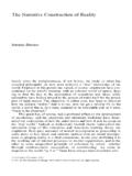
1 1 PRINCIPLES OF OPERATION 1. The rules of laser displacement measurements Displacement measurements with the use of laser allow obtaining the accuracy of 1ppm and bettering. The tool that allows such high accuracies is the interferometer, first built by Michelson in 1881. Its simplified schematic is shown on Fig. 1. Fig. 1. The Michelson interferometer. Coherent light beam fall on a self-transparent mirror. This mirror splits the light on two beams. The first goes to the reference arm and reflects from the reflector Z1; the second goes to the measurement arm and reflects form the reflector Z2. The reflected beams meet again on the detector. Because these beams come from the same, coherent, source, they will interfere.
2 DetectorZCoherentlightsourceReferenceref lectorMovingreflectormfDf1f1f1f1xfDZ1Z2f 1- frequency resulting fromthe Doppler effectfDvc2f1fD= 2 When the moving reflector is being displaced, the frequency of the reflected beam in the measurement arm changes. The detector counts the frequency difference between reflected beams fD (see Fig. 1). The measured value of displacement is obtained according to 22* ==NfLD (1) Where: N number of pulses, - light wavelength. The construction of real interferometers The main disadvantage of Michelson interferometer results from the fact that the detector does not determine, whether fD is negative or positive, thus from the measurements one obtain the displacement of the moving reflector without the sign.
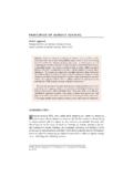
3 Currently there are widely used two methods that allow to get also the direction of the movement. Depending on the number of light frequencies (wavelengths) used in the interferometer, the first is called homodyne (one frequency) and the second heterodyne (two frequencies) method. In the homodyne method, shown on Figure 2, as a coherent source of light is used linearly polarized laser. If it is two-mode laser ( it generates two wavelengths) than one mode must be cut off with the use of a properly set polarizer. The polarising splitter splits the light beam from the laser on two beams polarized vertically (90o) and horizontally (0o). The former is directed to the measurement arm and the latter to the reference one.
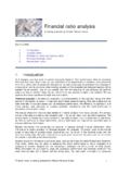
4 The frequency of the beam in the measurement arm changes with the movement of the moving reflector. The polarization of the reflected beams is changed to circular with the use of a /4 waveplate. Setting polarizers to angels 0 and 45 two signals shifted in phase are obtained. The phase shift is +90o when the measurement arm moves to and -90o when it moves from the laser. 3 Fig. 2. The block diagram of an interferometer working according to the homodyne method. In the heterodyne method, shown on Figure 3, two laser frequencies are used. Therefore a two-frequency laser is needed, a Zeeman laser. A two-mode laser is not suitable for heterodyne method interferometer, because the difference between f1 and f2 is usually too high for an electronic counter.
5 The output beam of a Zeeman laser consists of two circularly polarized subbeams , one polarized leftward and the second rightward. A /4 waveplate changes circular polarization to linear. The main difference between two described methods is that in the heterodyne one the beam frequency in reference arm differs from the beam frequency in the measuring arm. A detection path is also different the measurement is done by subtracting differential frequencies of reference and measuring arms. Polarizer 0 Pulse counterReferencereflectorPolarizingsplit terPhotodetectorsPolarizer 45 /4 Movingreflectorf2f1mfDmfDf1f1f1f1f1f1f2f 1 Two perpendicularlinear polarizations- frequency resulting fromthe Doppler effectfDxfDvc2f1fD=sincosvertical polarizationhorizontal polarizationpolarization +45polarization -45ooooTwo-modelaser 4 Fig.
6 3. The block diagram of an interferometer, working according to the heterodyne method. The heterodyne method gives correct results only when fD does not exceed the difference between the laser frequencies, : f2 f1. In reality, that difference, resulting from the Zeeman effect, is about 1 MHz. This limits the maximum available velocity of measuring arm, in one direction, to m/s. The next disadvantage of the heterodyne method is, that two frequencies must be used for measurements, while in the homodyne method the second may be used for measuring a second axis. Zeeman laserReferencereflectorPolarizingsplitte rPhotodetectors /4 Movingreflectorf1mfDf1f1f1f1f2 Two circularpolarizationsTwo perpendicularlinear polarizations- frequency resulting fromthe Doppler effectfDxfDcf2f2f2f2mfDf2f1 CounterCounterSubstractorPolarizersf1-f2 -()f2f1mfDNonpolarizingsplitterReference pathMeasurementpathv2f1fD=vertical polarizationhorizontal polarization 5 The influence of the outside conditions on the measurement accuracy According to equation (1) an interferometer s unit of measure in length measurement is laser s wavelength.
7 From definition fv= (2) a wavelength depends on laser s frequency f and the speed of light v in the measuring path. If the measurement is done in vacuum, than = c = 3*108 m/s. The speed of light in a medium other than vacuum ( air, water) is lower and is described as ncv= (3) Where: n a refraction coefficient. Normally the refraction coefficient n is a complex variable or even a tensor, but for less accurate calculations it is simplified to a constant. The air coefficient depends mostly on the pressure P, temperature T and humidity H.
8 The dependence nT,P,H, for the air was empirically determined by Edien and is described as nTTPPnHPT ++ += *003661,01)*00997,0613,0(**101*10*8775,2 167,, (4) TeHn*057627,09**10*033,3 = (5) From the above equations one may obtain the refraction coefficient dependences on T, P and H in usual conditions (T=293K, P=1000hPa, H=50%): = KTn110*93,06 += hPaPn110*27,06 = %110*96,08Hn It is worth to notice that the most critical parameter is the temperature, because its change influences the coefficient n more than changes in the pressure and much more than changes in the humidity.
9 6 2. The accuracy of laser interferometers Errors caused by the environment The most impotent source of errors in machine geometry measurements is the temperature (or more exactly, the change of the temperature) of the measured machine. For example, if the machine s base is made of steel, than the base s length increases m when its temperature changes 1K. It shows how important it is for very precise measurements to measure the temperature of the controlled part of the machine and to use it in readout corrections. This is not a simple task for a few reasons, but the most important one is that, than when the machine operates, there are temperature gradients on it.
10 That means that more than one temperature sensor is needed and that the more sensors are used the better accuracy can be achieved. Moreover the shape of the measured part of the machine may absorb a part of the expansion of the material or the part may be built of materials of different expandability. As was mentioned in the previous chapter, the temperature influences the accuracy also as it changes the refraction coefficient of the medium the measurements are made in (usually it is air, but may be water). An Edien equation was presented, showing how the refraction coefficient of the air changes with the change of the air temperature, pressure and humidity. The errors caused by the change of the wavelength are less important than the mentioned above, but they cannot be abandoned.