Transcription of Technical Seminar Manual - ICEWeb
1 anderson GREENWOOD CROSBY Technical Seminar Manual 2001 Tyco valves & Controls iTechnical Seminar ManualContentsSection I - Terminology .. 1 Section II - PRV Design .. 3 Section III - ASME Code .. 19 Section IV - DOT Code .. 25 Section V - Sizing .. 29 Section VI - Installation .. 45 Section VII - Valve Types .. 55 Section VIII - PRV Document Index .. 57 Section IV - Back Pressure .. 59 Section X - Flow Factor .. 63 Section XI - Flow Losses .. 67 anderson GREENWOOD CROSBY Technical Seminar Manual 2001 Tyco valves & Controls 1 TerminologyReference on definitions is API RP 520, Part I, SixthEdition (March 1993). Pressure Relief DevicesA. Pressure Relief Device:Adevice actuated by inlet stat-ic pressure and designed to open during an emergencyor abnormal conditions to prevent a rise of internal fluidpressure in excess of a specified value. The device mayalso be designed to prevent excessive internal device may be a pressure relief valve, a non-reclos-ing pressure relief device, or a vacuum relief Spring Loaded Pressure Relief Valve:Apressurerelief device designed to automatically reclose and pre-vent the further flow of Relief Valve:Apressure relief valve actuated by thestatic pressure upstream of the valve.
2 The valve opensnormally in proportion to the pressure increase over theopening pressure. A relief valve is used primarily withincompressible Safety Valve:Apressure relief valve actuated by thestatic pressure upstream of the valve and characterizedby rapid opening or pop action. A safety valve is nor-mally used with compressible Safety Relief Valve:Apressure relief valve that maybe used as either a safety or relief valve, depending onthe Pressure Relief Valve:Aspring-loadedpressure relief valve whose performance characteristicsare directly affected by changes in the back pressure onthe Balanced Pressure Relief Valve:Aspring-loaded pressurerelief valve that incorporates a means for minimizing theeffect of back pressure on the performance Pilot Operated Pressure Relief Valve:Apressure reliefvalve in which the main valve is combined with and con-trolled by an auxiliary pressure relief Rupture Disc:Anon-reclosing differential pressure reliefdevice actuated by inlet static pressure and designed tofunction by bursting the pressure-containing rupture disc device includes a rupture disc and a rup-ture disc Dimensional Characteristics ofPressure Relief DevicesA.
3 Actual Discharge Area:The measured minimum netarea that determines the flow through a Curtain Area:The area of the cylindrical or conical dis-charge opening between the seating surfaces above thenozzle seat created by the lift of the Equivalent Flow Area:Acomputed area of a pressurerelief valve, based on recognized flow formulas, equal tothe effective discharge Nozzle Area:The cross-sectional flow area of a nozzleat the minimum nozzle Huddling Chamber:An annular pressure chamber in apressure relief valve located beyond the seat for the pur-pose of generating a rapid Size:The nominal pipe size (NPS) of the valve atthe inlet connection, unless otherwise Outlet Size:The nominal pipe size (NPS) of the valve atthe discharge connection, unless otherwise Lift:The actual travel of the disc away from the closedposition when a valve is Operational Characteristics SystemPressuresA. Maximum Operating Pressure:The maximum pres-sure expected during system Maximum Allowable Working Pressure (MAWP):Themaximum gauge pressure permissible at the top of a com-pleted vessel in its operating position for a designated tem-perature.
4 The pressure is based on calculations for eachelement in a vessel using nominal thicknesses, exclusive ofadditional metal thicknesses allowed for corrosion and load-ings other than pressure. The maximum allowable workingpressure is the basis for the pressure setting of the pres-sure relief devices that protect the Design Gauge Pressure:The most severe conditionsof coincident temperature and pressure expected duringoperation. This pressure may be used in place of themaximum allowable working pressure (MAWP) in allcases where the MAWP has not been established. Thedesign pressure is equal to or less than the Accumulation:The pressure increase over the MAWPof the vessel during discharge through the pressure reliefdevice, expressed in pressure units or as a %. Maximumallowable accumulations are established by applicablecodes for operating and fire Overpressure:The pressure increase over the set pres-sure of the relieving device, expressed in pressure unitsor as a %.
5 It is the same as accumulation when therelieving device is set at the maximum allowable workingpressure of the vessel and there are no inlet pipe lossesto the relieving Relieving Capacity:That portion of the meas-ured relieving capacity permitted by the applicable codeor regulation to be used as a basis for the applicationof a pressure relief Stamped Capacity:The rated relieving capacity thatappears on the device nameplate. The stamped capac-ity is based on the set pressure or burst pressure plusthe allowable overpressure for compressible fluids andthe differential pressure for incompressible PressuresH. Set Pressure:The inlet gauge pressure at which thepressure relief valve is set to open under service Cold Differential Test Pressure:The pressure atwhich the pressure relief valve is adjusted to open onthe test stand. The cold differential test pressureincludes corrections for the service conditions of backpressure or temperature or Back Pressure:The pressure that exists at the outletof a pressure relief device as a result of the pressure inthe discharge system.
6 It is the sum of the superim-posed and built-up back Built-Up Back Pressure:The increase in pressure inthe discharge header that develops as a result of flowafter the pressure relief device Superimposed Back Pressure:The static pressurethat exists at the outlet of a pressure relief device at thetime the device is required to operate. It is the result ofpressure in the discharge system coming from othersources and may be constant or Blowdown:The difference between the set pressureand the closing pressure of a pressure relief valve,expressed as a percentage of the set pressure or inpressure Opening Pressure:The value of increasing inlet staticpressure at which there is a measurable lift of the discor at which discharge of the fluid becomes Closing Pressure:The value of decreasing inlet staticpressure at which the valve disc reestablishes contactwith the seat or at which lift becomes :The audible or visible escape of compressi-ble fluid between the seat and disc at an inlet staticpressure below the set pressure and at no Leak-Test Pressure:The specified inlet static pres-sure at which a seat leak test is Relieving Conditions:The inlet pressure and temper-ature of a pressure relief device at a specific overpres-sure.
7 The relieving pressure is equal to the valve setpressure (or rupture disc burst pressure) plus the over-pressure. (The temperature of the flowing fluid at reliev-ing conditions may be higher or lower than the operat-ing temperature). anderson GREENWOOD CROSBY Technical Seminar MANUAL2 2001 Tyco valves & ControlsFigure 1-1. Terminology (Examples of terms 3A, 3B, 3C, 3D, 3E, 3H, 3M, 3O, 3Q)Pressure VesselRequirementsVesselPressure Typical Characteristics of Pressure Relief ValvesSingle valveMaximum relievingpressure for processsizing(3E)Overpressure(maximum)(3 H) MaximumAllowable SetPressure for single valve(3P) Simmer(typical)Start to open(3M) Blowdown(typical)(3Q) Closingpressure(3Q) Leak test pressure (typical)859095100105110115120% of maximum allowable working pressure (gauge)(3A) Maximumexpected operating pressure)(3B,C) MaximumAllowable WorkingPressure or design pressure)(3D) AccumulatedPressure (other thanfire exposure)Section IANDERSON GREENWOOD CROSBY Technical Seminar Manual 2001 Tyco valves & Controls Pressure Relief Device DesignSection 2 describes pressure relief device standards,types, and operation and performance.
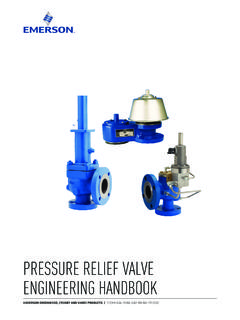
8 This information isprovided to assist you in efficiently specifying, using, andservicing pressure relief Standards and CodesThe following documents govern the design of PRVs: American Petroleum Institute (API) Standard 526,Flanged Steel Safety Relief valves American Society of Mechanical Engineers (ASME)Section VIII, Division I, Pressure Vessel Code,Paragraphs UG-125 through UG-136. ASME Section I, Boiler Code, paragraphs PG ASME Section III for Nuclear Pressure Vessels. ASME Section IV for Hot Water 526 lists inlet/outlet flange sizes and ratings for differentset pressure ranges, orifice sizes, materials and center to facedimensional standards. API 526 is a standard, not a , compliance is not mandatory to meet codes specify the following criteria: performance requirements material requirements set pressure spring design acceptable failure modes nameplate data capacity certification proceduresASME code-compliance is mandatory in applicable jurisdic-tional areas.
9 A few states have no law for unfired pressurevessels. However, for insurance purposes, most usersrequire code-stamped valves . All states require compliancewith the Boiler Design ConsiderationsAPRVis a safety device, intended to protect life and propertyif all other safety measures fail. Its main purpose then, and thefunction it must successfully accomplish when it operates, is toprevent pressure in the system being protected from increas-ing beyond safe design limits. A secondary intent of a PRV isto minimize damage to other system components due to oper-ation of the PRV itself. From a user's perspective then, thesedesign features should be considered in a valve design: leakage (if any) at system operating pressure is withinacceptable standards of performance opens at specified set pressure, within tolerance relieves the process product in a controlled manner closes at specified reseat pressure easy to maintain, adjust, and verify settings cost effective maintenance with minimal downtime andspare parts Valve TypesThe two general types of PRVs, direct-acting and pilot oper-ated, are explained in the Sections and respec-tively.
10 PRV operation is detailed in Section Direct-Acting PRVsThe oldest and most commonly used type of PRV is thedirect-acting type. They are designated as direct actingbecause the force element keeping the valve closed iseither a weight or a spring or a combination of both. Theprocess to be relieved acts directly on a seat pallet ordisc, which is held closed by the weight of a spring oppos-ing the lifting force ofthe process the lifting forcesand opposing forcesare equal, the valve ison the threshold 1. The ASME code applies only to pressure relief valves set at or above15 psig. Figure 2-1. Early Design PRV (Circa 1900)Figure 2-2. Weight-Loaded Vacuum PRVO verpressure ProtectionAir InletTank ConnectionVacuum ProtectionSection IIANDERSON GREENWOOD CROSBY Technical Seminar MANUAL4 2001 Tyco valves & ControlsThere are two kinds of direct-acting type PRVs, weight-loaded and direct-acting, weight-loaded PRV was the first type ofPRV to be used.