Transcription of How to Load Parts in Furnace Baskets B - Heat …
1 How to load Parts in Furnace BasketsBecause Parts come in all shapesand sizes, standard heat treatingfurnaces have been designed to ac-commodate most any workload con-figuration (Table 1). A loadingarrangement generally falls into oneof two classes: weight limited orvolume limited. In either case, whenloading Parts in Furnace Baskets oronto racks the goal is often to maxi-mize loading efficiency. However,heat treaters must also be concernedwith proper part spacing; that is, po-sitioning Parts within the load for op-timal heat transfer, atmosphere circu-lation, temperature uniformity, andheat extraction during quenching tominimize distortion. Despite the al-most limitless choices, some com-monsense rules factor: How Parts areloaded is very much a function of thestyle of Furnace being used.
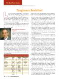
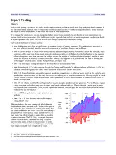
2 Rectan-gular Baskets designed for stacking ornesting (Fig. 1) are commonly used inintegral quench furnaces. These aretypically placed atop carrier grids. Pitfurnaces use cylindrical Baskets , oftenwith solid sides (Fig. 2) to promote cir-culation. In some instances, Parts areloaded onto fixtures consisting of mul-tiple grids with a center post a Christmas tree arrangement ( ). Parts loaded in pusher-style fur-naces can be placed directly on thegrid, in racks, or in segmented framesAbout the columnist .. Daniel H. Herring is president of The Herring Group Inc., Elmhurst, Ill., a businessspecializing in practical solutions to problemsfacing the heat treating and sinteringindustries (Web: ).
3 Dan Herring has spentmore than 25 yearsworking for Furnace equip-ment manufacturers in avariety of roles, includingsenior management andnew business an independent entrepreneur, Dan lectures, writes, teaches, and consults. A fre-quent speaker at local, national, and interna-tional conferences, he is dedicated to advancingthe state of the art in thermal processing. He has published more than 100 technical papers, written three books, and contributesto Heat Treating Progressand other in-dustry s credentials include his appointmentas a research associate professor at the Ther-mal Processing Technology Center, Illinois In-stitute of Technology, Chicago. He also is activeon several HTS TREATING PROGRESS NOVEMBER/DECEMBER 2003 17 Generic and practical information presentedhere is not intended to replace or supplementfederal, state, and local codes, governmentstandards, insurance requirements, companypolicies and procedures, or common sense.
4 Inaddition, all equipment manufacturers in-structions and operating and maintenancemanuals should always be thoroughly readand followed. Further, personnel trainingshould be provided unequivocally to everyonewho will be associated with operating suchequipment. Table 1 Common Furnace workload sizesFurnace styleWidth, , , , , in. Pit12 12012 192 Fig. 1 Baskets of precision-machined AISI/SAE 8620 (UNS G86200) steel plates will becarburized and oil quenched in a batch integral quench Furnace . The Parts Baskets are made ofAISI 330 (UNS N08330), an austenitic Ni-Cr-Fe-Si alloy combining resistance to carburizationand oxidation at temperatures to 2200 F (1200 C) with high strength. Photo courtesy Specialty HeatTreating Inc.
5 , Grand Rapids, Mich. ( ). 11/16/03 4:37 PM Page 1having crossmembers that can beadded or removed as dictated by thegeometry of the part to allow forhanging or support (Fig. 4).Determining part spacingThe orientation of Parts in the work- load is very important when trying tominimize distortion in heat loading Baskets , imagine thateach part occupies a cylindrical spaceencompassing both the part and a sep-aration space or gap between it andadjacent Parts (Table 2).An example is the load configura-tion for a part having overall dimen-sions of in. diameter 4 in. part will fit inside a typical cylin-drical envelope of in. ( + ) diameter in. (4 + in.)high. Bear in mind that there are ex-ceptions to every rule, and these partspacing recommendations are basedon practical experience.
6 Denserloading may be possible, but it is agood idea to have empirical test re-sults and quality checks to prove thatit can be done. An example: a load in. OD shafts placed into 24 36in. Baskets having openings that mea-sure only in. final part spacing selected isdictated by concerns for heating,soaking, and atmosphere flow; thevolume and type of quench medium(brine, water, polymer, oil, salt, or air);and gross load weight. There are sev-eral industry-tested rules of thumbthat can be used to help determine theproper spacing around Parts , althoughtrial-and-error is usually the bestmethod. In general, the gap around apart should be no less than 25% andno greater than 75% of its envelope :Note that both process andequipment variables also must be fac-tored in.
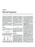
7 For example, large- andmedium-sized bearing races of var-ious diameters are commonly nestedinside one another to produce an op-tically dense workload. This is donebecause the Furnace space is volumelimited, not weight limited. However,THE HEAT TREAT DOCTORC ontinuedFig. 2 Circular basket for a large pit Furnace , left. (Source: ASM Handbook, Vol. 4, HeatTreating: ASM International, Materials Park, Ohio, 1991, p. 515.) Stack of fabricated Baskets ,right. (Source: Rolock Inc. advertisement, Metal Progress, Vol. 114, No. 4, September 1978, Rolock went out of business in 2001. Many of the alloy components formerly made by Rolockare now fabricated by Alloy Engineering Co., Berea, Ohio.)Fig. 3 Pit Furnace lifting post fixture.
8 Thefixture is being inspected by Michael Haite(right, in white shirt), director of alloy fabri-cator AFE Klefisch, H rth, Germany, and en-gineers of customer Timken Rom nia ,Ploiesti. Photo courtesy North AmericanCronite Inc., Div. AFE Technologies Corp.,North Ridgeville, 4 Tray/fixture assembly for carburizing pinions, left. (Source: ASM Handbook, Vol. 4,Heat Treating, p. 515.) Heat treat fixture with gridsand posts, center. (Source: North American Cronite Inc., Div. AFE Technologies Corp., North Ridgeville, Ohio.) Do-it-yourself fixturing: the ultimatein adaptability, right. (Source: Rolock Inc. advertisement, Metal Progress, September 1978, p. 8.)Table 2 Typical part spacing requirementsPart diameter, spacing (inside), spacing (inside), in.
9 < >4>3>218 HEAT TREATING PROGRESS NOVEMBER/DECEMBER 11/16/03 4:37 PM Page 2 THE HEAT TREAT DOCTORC ontinuedthe cycle must be adjusted to allowenough time for the interior Parts tobe heated. In a case like this, thespacing given in Table 2 is often dou-bled. On the other hand, when pro-cessing similarly shaped Parts madeof thin-wall tubing, but not nestingthem, the spacing is often reduced dueto the relative ease of heating part loading:The mostcommon reason to shovel- or random- load Parts is to reduce labor bearing races 1 in. in diametercould be stacked but instead arerandom loaded to a depth that will notprevent successful quenching, but willmake it difficult to circulate furnaceatmosphere throughout the load .
10 Tocompensate, heat treaters push asideparts to create empty spaces, often atthe center of the load . This preservesthe economic advantage of randomloading, since it would take muchlonger to stack the small Parts to en-sure proper atmosphere calculationsWhen loading rectangular Baskets ,there s a simple formula for deter-mining how many circles of a givendiameter (how many Parts ) can beplaced into a rectangle of known size:W/d L/d = N,where W is the width of the rectan-gular space, L its length, d is the di-ameter of the part (including the sep-aration space), and N is the numberof Parts that can be loaded into the rec-tangular :(In this calculation all frac-tional Parts are rounded down.) Con-sider a Furnace with a workload sizeof 24 in.