Transcription of Extra Room Power Heat Duct Instructions
1 Extra Room Power Heat duct Instructions SKU 98500769 Page 1 of 8 11/4/19 - 17601067 Travis Industries, Inc. Compatibility FIREPLACE MAX. # OF Power HEAT DUCTS 3615 2 4237 2 4415 2 6015 2 564 HO 2 864 31K CF and Louvered 1 864 40K TV CF and Louvered 1 864 ST 1 Packing List Blower Box duct Adapter (6 Round to 10 by 3-1/4 ) 6 Round duct (2 to 20 Length) Rheostat Rheostat Knob Grill (with 2 screws) Wall Adapter 2 Junction Boxes Cover Plate (w/ screws) Floor Boot 4 #8 Sheet Metal Screws Wall Mounting Brackets (2)
2 Starter Ring (4) #8 Wood Screws Installation Warnings Warning: This kit must be installed as specified in these Instructions . Do not modify any component. Warning: Use of any external blower other than the Travis Power Heat duct Blower will void the warranty and listing of this appliance and may create a fire hazard. Note: The Power heat duct must be installed by a qualified service technician. Note: Some building codes may require the use of firestop spacers whenever the duct passes from room to room. Note: When routing ducts through a cold area ( crawl space) we recommend insulating the duct with fiberglass insulation.
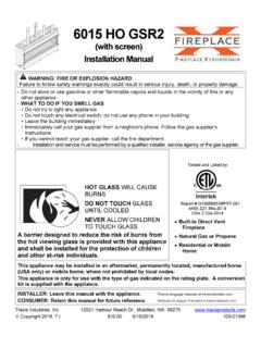
3 If paper-backed insulation is used, the paper can not contact the duct . Starter Ring Installation on Fireplace The included starter ring is attached to the fireplace. See the fireplace installation manual (included with the fireplace) for details on installing the starter ring. Additional cover plates inside the fireplace may need to be removed for this kit to work correctly. Extra Room Power Heat duct Instructions SKU 98500769 Page 2 of 8 10/4/16 - 17601067 Travis Industries, Inc. Installation Overview The illustration below shows an overview of a typical installation. Install the heat duct prior to installing drywall.
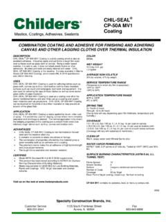
4 Starter RingUse 10 x 3-1/4 wall stack ( duct ) when passing through tight " DuctDuct Adapter (6 Round to 10 x 3-1/4 )Floor BootGrillRheostat (with cover plate)Junction BoxWall Adapter (for use on 2 x 4 walls)Blower BoxMaximum duct Length = 20'Electrical Source Extra Room Power Heat duct Instructions SKU 98500769 Page 3 of 8 10/4/16 - 17601067 Travis Industries, Inc. duct Installation duct Routing Determine the route for the heat duct using the illustration below as a guide. Blower Mounted in Wall or Ceiling * This blower was designed for framing on 16" centers. Construct additional framing if needed. If the blower is installed prior to the drywall only a 14" opening is required.
5 If installed after the drywall is in place, the drywall to the sides of the blower will need to be patched. Use 10 x 3-1/4 wall stack ( duct ) when passing through tight Maximum LengthDuct Adapter (6 Round to 10 x 3-1/4 - included with the Power heat vent kit)Blower Box0 Clearance to CombustiblesCo-Axial Vent (for intake air and exhaust)NOTE: Air flow through the duct is affected by length and number of bends. Keep the length and number of bends to the minimum to maximize performance. When the duct penetrates the fireplace enclosure vertically and the top of the enclosure is within 36 of the top of the fireplace, a firestop spacer that maintains a 1/2 clearance between all sides of the duct and any combustible material must be used.
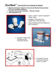
6 1/2 bAttach the wall mounting brackets to the blower the bracket to these holes for 2 x 4 wallsMount the bracket to these holes for 2 x 6 wallsCut a hole between wall framing members for the blower 5-1/4"16"*cSlide the blower, with wires, into the hole cut in step "a". Attach with four screws. Extra Room Power Heat duct Instructions SKU 98500769 Page 4 of 8 10/4/16 - 17601067 Travis Industries, Inc. Blower Mounted in Floor Attaching duct to Fireplace Attach the starter ring to the fireplace following the directions below (some fireplaces have one opening, some two use the most convenient side). Cut a hole between floor joists for the blower box.
7 5-1/4"14"abcAttach the floor boot to the blower box with the included the blower into the hole cut in step "a". Attach with four screws. The screws attach to either of these pairs of holes. Use the upper pair for thick flooring, the lower pair for thin the tabs on the bottom of the starter ring up to lock it in " NutdriverRemove and discard the cover Ring Extra Room Power Heat duct Instructions SKU 98500769 Page 5 of 8 11/2/18 - 17601067 Travis Industries, Inc. duct Installation Each duct connection must be secured with three screws and aluminum duct tape ( 181A-P or equivalent). Secure the duct if it is in an area where it may sag or become dislodged (use plumbing straps or other suitable means).
8 NOTE: You may need to crimp the floor boot to allow the flex duct to fit over the opening. NOTE: Additional ducting of similar cross section may be used (see illustration below). NOTE: The air duct has a 0 clearance to combustibles. Grill Installation Attach the grill (and wall adapter, if necessary). Secure all ducting together with screws. Then seal the seams with aluminum duct tape ( 181A-P or equivalent).GrillWall Adapter (for use when the blower box protrudes from the wall - primarily on 2 x 4 walls) Phillips ScrewdriverScrews (included with this kit) Extra Room Power Heat duct Instructions SKU 98500769 Page 6 of 8 10/4/16 - 17601067 Travis Industries, Inc.
9 Wiring Instructions Warning: All wiring should be done by a qualified electrician and shall be in compliance with local codes and with the current National Electric Code ANSI/NFPA 70 (in the ), or with the current Canadian Electric Code (in Canada). Warning: Make sure the fireplace electrical circuit is disabled prior to working on electrical hookup. Wiring Diagram Hot (black)Common (white)Ground (green) Power SupplyHot (black)Common (white)Ground (green)Rheostat Junction BoxBlower Assembly Extra Room Power Heat duct Instructions SKU 98500769 Page 7 of 8 10/4/16 - 17601067 Travis Industries, Inc. Blower Box Wiring Rheostat Junction Box Wiring NOTE: There are two junction boxes included (new construction and retrofit).
10 Use the appropriate junction box for your installation. Remove the cover from the blower sheathed cable through the cable clamp. After the wires have been connected tighten the clamp to secure the the ground wire to the ground stud inside the blower box by tightening the included nut over the ground wire. Re-attach the cover removed in step "a".Attach the hot (black) and common (white) wires to the leads coming from the wires (use wire nuts).cdStandard ScrewdriverPhillips ScrewdriverGround WireaForce the sheathed cable through one of the locking flaps on the junction box (repeat for the other cable). Some force is needed.