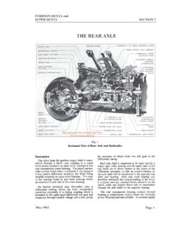
Transcription of THE FRONT AXLE - Tractor Spares
1 FORDSON DEXTASECTION 2 Page 1 Feb. 1958 The FRONT axle consists of a centre beam, mountedto the FRONT engine support by means of a trunnionpin, and right- and left-hand extension units whichcarry the wheel spindles. Two radius rods areconnected between the centre beam and the gearboxhousing to provide rigidity for the FRONT standard tyres, the FRONT wheelsare adjustable from 48 ins. to 76 ins. in 4 in. stageswhen the extension units are symmetrically optional rims and tyres the smallestpossible track setting is 52 ins. otherwise the tyreswill rub on the radius rods when on maximum cast figures on the outer axle beams indicatethe track width when both outer axle beams aresymmetrically positioned.
2 Figures marked on thetop flange of the outer axles (Fig. 2) indicate thetrack width when they line up with the innermosthole (Hole A) of the centre beam. Similarly, thefigures on the bottom flange indicate track widthwhen lined up with the outermost hole (Hole B) ofthe centre Track least one open bolt hole must beleft between the axle beam to extension fixing wheels must not be reversed on the hubs toobtain a greater track since this results in excessiveloading on the bearings and mounting track settings at, or below, 56 ins. the radiusrods should be located in the inner holes (Hole C,Fig. 2) of the centre beam, but when the track isadjusted to over 56 ins.
3 The radius rods must bemoved to the outer holes (Hole D) to the track has been re-set it will be necessaryto adjust the toe-in as described below, both draglinks being adjusted to ensure equal of the FRONT wheels is designed to be betwen1/4 in. ans 1/2 in. and may be regulated by adjusting thedrag links. Correct toe-in is set at the factory andmarked with four chisel marks, one on each spindlehousing lining up with one on each steering new steering arms are fitted it will be necessaryto re-align the wheels and re-mark for future FRONT AXLEFig. 1 The FRONT AxleFree Download DEXTA FRONT AXLESECTION 2 Page 2If only one steering arm is to be changed, set thesteering in the straight ahead position, using themarks on the opposite steering arm and axle extensionas a the new arm, connect its corresponding draglink and measure between the FRONT wheels (at bothfront and rear) at hub the drag link until the correct toe-in of1/4 in.
4 To 1/2 in. is obtained. Chisel mark the new armin line with the existing mark on the axle circumstances arise where it is not possibleto use the original factory marking ( if the marksbecome obliterated or if both steering arms or bothaxle extensions require renewing) it will be necessaryto find first the centre of the steering the drag link and count the numberof turn required to move the steering wheel fromlock to lock, then turn the wheel back half thisnumber of the new parts and place the wheels inthe straight ahead position, connect the drag linksand adjust their lengths to give the specified mark the arms and axle extensions adjusted length of the drag links differbecause of the position of the steering drop armsand, if fitting new drag links or drag link ends, thelength of each drag link will have to be adjustedindividually.
5 The approximate lengths of the draglinks with track at 52 ins. (132cm) are: ins. (99,3cm) and ins. (97,5cm).The FRONT and rear drag link ends also differ asshown in , and care must be taken to ensurethat the links are fitted is most important that the drag link tubeto drag link end clamp bolts are alwayspositioned so as to lie across the split in Pin and BushTo RemoveTo Replace1. Disconnect the two radius rods from the centrebeam and the drag links from the steering Jack up the FRONT of the Tractor to just supportits weight and remove the FRONT axle extension Remove the trunnion pin clamping bolt andretainer and draw out trunnion pin, using ToolNo.
6 Ensure that the spacers are maintainedin their originally assembled Slide out the centre beam Drive out the trunnion pin bush using Tool Fit a new bush using Tool andcheck the fit of the trunnion pin in the Slide the centre beam into position and align itwith the FRONT axle Replace the trunnion pin, remembering to fit thelarge spacer between the FRONT of the centre beamand the axle support. The other spacers are fittedin the position they were in before Refit the trunnion pin retainer and Replace the axle extension units checking thatthe fixing bolts are located in the correct 2 Track SettingsFig. 3 FRONT and Rear Drag Link EndsFree Download 1958 FORDSON DEXTA FRONT AXLESECTION 2 Page 3 Feb.
7 19586. Connect the radius rods to the centre axle Connects the drag links to the steering arms andcheck that the wheel alignment marks are Remove the jackThe following applies to both left- and right Jack up the FRONT of the Tractor , grasp the wheelat the top and bottom and test for excessive play inthe bearings. (Do not mistake worn wheel spindlesor bushes for end play in the bearings.)2. Remove the hub cap and extract the split pin fromthe bearing adjusting Rotate the wheel whilst tightening up the bearingadjusting nut and continue to tighten until a heavydrag can just be felt. Turn back the nut, one castella-tion at a time so that the wheel rotate freely, butwith no end play. Fit a new split pin and reassemblethe hub cap filled with clean grease.
8 Finally lowerthe Tractor to the bearings should be tested for correct adjust-ment every 200 working hours and readjusted ifnecessary. Even if it is not necessary to adjust thebearings the hub cap should be removed and filledwith clean Care should be taken to ensurethat no dirt or water is allowed to reach the bearings,or inside the hub cap when the wheels are beingreadjusted1. Remove the hub cap and jack up the FRONT wheelof the Extract the split pin from the bearing adjustingnut and remove the nut and keyed BearingsTo AdjustTo RemoveFig. 4 Trunnion Pin RemovalFig. 5 Removing the Spindle Bushes3. Pull the wheel outwards so that the outer bearingcan be detached and lift the wheel off the The inner bearing can now be removed and ifthe dust excluder needs replacing it can be leveredoff its If the bearings need replacing press out the innerand outer bearing cup using Adaptors Tool No.
9 Fit the new inner and outer bearing cups usingAdaptors in Tool No. and pack thehub with a good quality short fibre Fit a new dust excluder if required (using ToolNo. ) and replace the inner bearing on Lift the assembly onto the spindle and locate theouter bearing and keyed Fit the adjusting nut and adjust the bearings aspreviously Fit the new split pin and reasemble the hub capfilled with clean Remove the up the FRONT of the Tractor and remove Disconnect the drag link to steering Remove the FRONT axle Slacken off the steering arm locking bolt, removethe steering arm, the woodruff key and the dust sealand slide out the wheel spindle (the bottom thrustbearing will come away with the wheel spindle.)
10 To ReplaceSpindle BushesTo RemoveFree Download 1958 Page 4 FORDSON DEXTA FRONT AXLESECTION 25. Pull out the bushes using Tool No. T3049 (seeFig. 5).6. Clean out the grease and any swarf left afterusing the Using Tool No. and 550 handle, fit thenew upper and lower bushes (see Fig. 6).2. Check the fit of the wheel spindle in the Refit the extension to the centre Assemble the thrust bearing on the wheel spindleensuring that it is correct way up and locatethe wheel spindle in Replace the dust seal and woodruff key and clampthe steering arm in Connect the drag link to the steering arm,checking that the wheel alignment marks areaccurately Refit the wheel and adjust the Remove the ReplaceFig.