Transcription of N7VE LED SWR Bridge - QRP Kits - Pacific Antenna
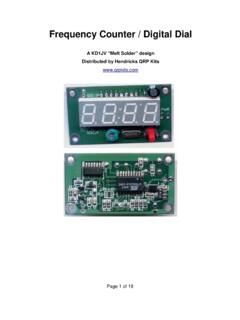
1 n7ve LED SWR Bridge v3 March 29, 2012 Page 1 of 10 n7ve LED SWR Bridge Hendricks QRP kits A simple, rugged and lightweight SWR Bridge by Dan Tayloe, n7ve n7ve LED SWR Bridge v3 March 29, 2012 Page 2 of 10 Table of Contents Kit Parts .. 3 Building the LED SWR Bridge .. 3 RF step up 4 Other top mounted 6 Bottom mounted 7 DPDT Switch mounted .. 8 Mounting the board to a case .. 9 Attaching the switch to the 9 Initial DC tests .. 10 Initial RF tests .. 10 Usage Caution! QRP power only! ~ 5w max!.. 10 List of Figures Figure 1. Kit bag of parts right out of the box .. 3 Figure 2. Contents of the bag 3 Figure 3. FT37-43 RF step up transformer with first 5 turns. Make loop for 5T tap.. 4 Figure 4. 25 turns total totally fills the 4 Figure 5. Close up view of the RF step up transformer with dressed 5 Figure 6. RF step up transformer mounted on the 5 Figure 7. Double check after mounting that the inductor is mounted properly.
2 6 Figure 8. Mounting D1, R4, and C1. Note the position and band orientation of the mounted 6 Figure 9. Pre-form the leads of thethree 51 ohm resistors as shown .. 7 Figure 10. Three 51 ohm power resistors mounted on the bottom side of the PC board .. 7 Figure 11. Switch shown mounted on the top side.. 8 Figure 12. Switch mounted to simulated front panel. LED not soldered 9 Figure 13. LED mounted and soldered to PCB.. 9 n7ve LED SWR Bridge v3 March 29, 2012 Page 3 of 10 Kit Parts Figure 1. Kit bag of parts right out of the box Figure 2. Contents of the bag identified Building the LED SWR Bridge Note: Order is important: LED last; Switch next to last, 51 ohm power resistors just before that. Note: This Bridge is for QRP only! 5w average power (10w PEP) max! n7ve LED SWR Bridge v3 March 29, 2012 Page 4 of 10 RF step up transformer Figure 3. FT37-43 RF step up transformer with first 5 turns. Make loop for 5T tap. Figure 4. 25 turns total totally fills the core.
3 n7ve LED SWR Bridge v3 March 29, 2012 Page 5 of 10 After winding the RF step up transformer as above, clip one side of the 5T tap loop. Next trim the leads as shown below: Figure 5. Close up view of the RF step up transformer with dressed leads After dressing the leads as above, take an ohm-meter, place it across the start and end leads above, and make sure that the ohm-meter shows a short (0 ohms). If this is not the case, the twisted leads at the 5T tap have not been properly soldered together. Figure 6. RF step up transformer mounted on the PCB n7ve LED SWR Bridge v3 March 29, 2012 Page 6 of 10 Figure 7. Double check after mounting that the inductor is mounted properly. These pads must be shorted! Using a ohm-meter check the three pads above to make sure that all of these pads show a short to each other. This makes sure that the RF step up transformer has been constructed and mounted properly. Other top mounted parts Figure 8. Mounting D1, R4, and C1.
4 Note the position and band orientation of the mounted D1 C1 has some crimps that I straightened out in order to mount it more flush to the top of the board as shown. R4 gets mounted now also n7ve LED SWR Bridge v3 March 29, 2012 Page 7 of 10 Make very, very sure diode D1 is mounted as shown above. D1 is mounted on end, with the band oriented up as shown. The LED does not get mounted until the very last step! Do not mount the switch yet! Bottom mounted parts Figure 9. Pre-form the leads of the three 51 ohm resistors as shown Figure 10. Three 51 ohm power resistors mounted on the bottom side of the PC board n7ve LED SWR Bridge v3 March 29, 2012 Page 8 of 10 DPDT Switch mounted Figure 11. Switch shown mounted on the top side. It is a bit hard to keep the switch flat while soldering it down. I suggest soldering down one corner, making sure the switch is flat, then soldering the opposite corner, and double checking the switch is indeed flat and level before finally soldering it down.
5 Do not despair if you don t get the switch completely level. It affects nothing but aesthetics as the board mounts using the switch hardware. Note the LED is not mounted yet. n7ve LED SWR Bridge v3 March 29, 2012 Page 9 of 10 Mounting the board to a case Attaching the switch to the case Figure 12. Switch mounted to simulated front panel. LED not soldered yet. Figure 13. LED mounted and soldered to PCB. The LED shown here is larger than that actually supplied. I personally like the smaller one better. I drilled LED the hole slightly smaller than the LED, then gradually enlarged the LED hole by spinning a tapered file in it until I got a snug press fit of the LED in its hole. Alternative epoxy could be used. n7ve LED SWR Bridge v3 March 29, 2012 Page 10 of 10 Initial DC tests Place an ohm-meter across the terminals market TX . With the toggle handle away from the LED (as shown in the figure above), the ohm-meter should show 75 ohms.
6 In this position, the SWR Bridge is in the circuit, allowing SWR readings to be taken. Place an ohm-meter across the terminals market TX . With the toggle handle towards from the LED (as shown in the figure above), the ohm-meter should show an open circuit. In this position, the SWR Bridge is out the circuit. This is the operate position that is used after the Antenna has been tuned for best SWR. Place an ohm-meter across the terminals market ANT . With the toggle handle away from the LED (as shown in the figure above), the ohm-meter should show 51 ohms. Place an ohm-meter across the terminals market ANT . With the toggle handle towards from the LED (as shown in the figure above), the ohm-meter should show an open circuit. Initial RF tests This test makes sure that both the diode D1 and the LED have been installed with the same polarity. If one of these were to be installed backwards, the LED will never light. Connect a QRP transmitter (5w max!)
7 To the TX terminal. Leave the Antenna connection open. Make sure the switch is positioned away from the LED (SWR Bridge is in the circuit). Send a single dit on the QRP transmitter and make sure the LED lights up. No Antenna is a worst case SWR situation. Optionally, a 50 ohm load can be connected to the Antenna side, and another single dit and make sure the LED is either out or very dim. Usage Caution! QRP power only! ~ 5w max! An LED SWR Bridge is almost always used with an Antenna tuner. When tuning up an Antenna using an Antenna tuner, first listen to the band background noise on the receiver, and try to peak the band noise using the tuner controls. This should get the tuner in the ball park. Next place the LED SWR Bridge into the circuit by placing the switch away from the LED. I suggest tuning up by sending a series of dots. A series of dots will keep your transmitter PA finals from overheating, as well as pulsing the LED on. Now adjust the tuner to get the minimum LED brightness.
8 Even a dim LED is a very good SWR level. The normal situation is to adjust the tuner until the LED goes out. This indicates a very good match. After the Antenna is tuned up, switch the Bridge out of the circuit by flipping the switch handle towards the LED. Keeping the Bridge in the circuit will reduce the power by a factor of four to a matched Antenna . This can occasionally be useful when trying to bring a 3w QRP transmitter to under the 1w level for certain sub-one watt contest multipliers.