Transcription of Technical Information Indumax CLS50/CLS50D - …
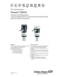
1 TI182C/07/ InformationIndumax cls50 / cls50 DInductive conductivity sensor for standard, hazardous and high-temperature applications, analog or digital with Memosens protocolApplicationIndumax CLS50/CLS50D conductivity sensors are especially suitable for application in the chemical industry and process engineering. The six-decade measuring range and the high chemical resistance of the materials in contact with medium (PFA or PEEK) permit to use this sensor in a number of various applications, : Concentration measurement of acids and bases Quality monitoring of chemical products in tanks and pipes Phase separation of product/product mixturesDigital cls50d sensors are used with the controller Liquiline CM442. Analog cls50 sensors are used with the transmitters Liquiline CM42, Liquisys CLM223/253 or Mycom benefits High durability High chemical resistance thanks to PFA coating PEEK version for high temperatures up to 180 C (356 F) Low risk of soiling Dirt-repellent PFA surface Large sensor opening Easy installation Can be installed in T-pieces DN 80 with the outgoing diameter reduced to DN 50 Total cable length up to 55 m (180 ft) Wide measuring range from 2 S/cm to 2000 mS/cm Integrated, coated Pt 100 temperature sensor, error class A Ex approval EEx ia IIC T6/T4 Indumax cls50 /CLS50D2 Endress+HauserFunction and system designMeasuring principleInductive conductivity measurementA generator (1) generates an alternating magnetic field in the primary coil (2) which induces a current in the medium (3).
2 The strength of the induced current depends on the conductivity and thus the ion concentration of the medium. The current flow in the medium generates another magnetic field in the secondary coil (4). The resulting current induced in the coil is measured by the receiver (5) and processed to determine the properties Wide measuring rangeThe sensor s measuring range comprises six decades, from 2 S/cm to 2000 mS/cm. DurabilityThe materials in contact with medium (PEEK, PFA) feature a very high chemical resistance. In addition, the PEEK version is suitable for application at high temperatures of up to 180 C (356 F). Low risk of soilingThanks to its large opening, the sensor is not susceptible to soiling. The PFA version requires even less cleaning thanks to its dirt-repellent of digital sensors with Memosens protocolDigital sensors are able to store the following system data in the sensor.
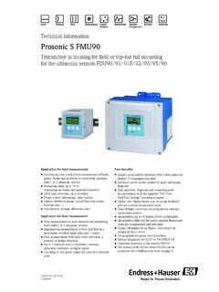
3 Manufacturing data Serial number Order code Date of manufacture Calibration data Calibration date Cell constant Change in cell constant Number of calibrations Serial number of the transmitter used for the last calibration Application data Temperature application range Conductivity application range Date of first commissioning Maximum temperature value Operating hours at high temperaturesa0004894 Inductive conductivity measurement12345 GeneratorPrimary coilCurrent flow in the mediumSecondary coilReceiverBenefits of inductive conductivity measurement No electrodes, therefore no polarization Accurate measurement in media or solutions with a high soiling degree and a tendency to deposition Complete galvanic separation of measurement and medium15432 Indumax cls50 / cls50 DEndress+Hauser3 Measuring systemCLS50DA complete measuring system comprises: a cls50d conductivity sensor with fixed cable a transmitter, Liquiline CM44xOptional: Weather protection cover for the field installation of the transmitter Assembly for sensor installation in tanks or in pipework, CLA111a0012990 Example of a measuring system1 Liquiline CM44x transmitter 2 Weather protection cover3 Pipe socket for flange DN50 PN/64 Sensor cls50d , flange version DN50 PN/6, fixed cable with M12 plug12345 Indumax cls50 /CLS50D4 Endress+HauserCLS50A complete measuring system comprises.
4 A cls50 conductivity sensor with fixed cable a transmitter, Liquiline CM42 Optional: Weather protection cover for the field installation of the transmitter Assembly for sensor installation in tanks or in pipework, CLA111a0007045 Example of a measuring system1 Indumax CLS502 Liquiline CM42 transmitter3 Weather protection cover4 Pipework5 Pipe socketInputMeasured variable Conductivity TemperatureCell constantk = cm 1 Measuring frequency2 kHzMeasuring rangeTemperature measurementPt 100 (class A acc. to IEC 60751)Conductivity: 2 S/cm to 2000 mS/cm (uncompensated)Temperature: 20 to +180 C (-4 to +350 F) Indumax cls50 / cls50 DEndress+Hauser5 WiringCable specificationThe sensor is supplied with a fixed cable. The connection to the transmitter can be extended using the CYK81 ( cls50d ) or the CLK5 ( cls50 ) special measuring ! Please note that the residual coupling increases when the cable is characteristicsMaximum measured error -20 to 100 C (-4 to 212 F): (5 S/cm + % of the measured value) > 100 C (212 F): (10 S/cm + % of the measured value)Temperature response time PEEK versions:approx.
5 7 min PFA versions:approx. 11 minInstallation conditionsInstallation positionInstall the sensor in such a way that the sensor opening is oriented in the flow direction of the medium. The sensor head must be completely immersed in the position of the sensor1 Flow direction of medium2 Minimum water level in the pipeaSensor distance from the pipe walla0013000 CYK81 for cable extension for cls50d max. total cable length: 100 m (330 ft)a0012998 CLK5 for cable extension for cls50 max. total cable length: 55 m (180 ft)GNBNWHYECOM ACOM BU+U WHRDPt 100 YEGNRDWHBUBN 100( )mm (inch) Indumax cls50 /CLS50D6 Endress+HauserInstallation factorIn narrow installation conditions, the conductivity measurement is affected by the pipe walls. This effect is compensated by the so-called installation factor. The transmitter corrects the cell constant by multiplication with the installation value of the installation factor depends on the diameter and the conductivity of the pipe as well as the sensor s distance from the wall.
6 If the distance from the wall is sufficient (a > 15 mm ( "), from DN 80), it is not necessary to consider the installation factor (f = ). If the distance from the wall is smaller, the installation factor increases in case of electrically insulating pipes (f > 1) and decreases in case of electrically conductive pipes (f < 1).The installation factor can be measured using calibration solutions or it can be approximately determined from the following between installation factor f and distance from wall a1 Electrically conductive pipe wall2 Insulating pipe wallAir setCLS50To compensate residual coupling in the cable and between the two sensor coils, you must perform a zero calibration in air ("air set") before installing the further Information , refer to the Operating Instructions of your digital sensor is already adjusted at the factory, an on-side compensation is not [inch]051015202525a [mm] cls50 / cls50 DEndress+Hauser7 Installation of sensors with flangeThe sensor is suitable for installation in T-pieces DN 80 with the outgoing diameter reduced to DN 50.
7 Warning! Danger of injuries by leaking medium Tighten the nut with a torque of at least 20 Nm. To avoid leakages, regularly check the tightness of the , not in contact with mediumFlange, in contact with mediuma0007061 Fixed flange, not in contact with medium (order option "process connection": 5, 6, 7)123 Flange (stainless steel)NutSealing disk (Gylon )45O-ringSensora0007062 Fixed flange, in contact with medium (order option "process connection": 3, 4)12 Flange (stainless steel)Nut34O-ringSensorIndumax cls50 /CLS50D8 Endress+HauserLap-joint flange, not in contact with mediumInstallation of sensor assemblyEnvironmentAmbient temperature range 10 to +70 C (+10 to +160 F)Storage temperature 20 to +80 C (-4 to +180 F)Ingress protectionIP 67 / NEMA 6 (installed with original sealing)a0007063 Lap-joint flange, not in contact with medium (order option "process connection".)
8 A, B, C)123 Lap-joint flange (PP-GF)Nut (stainless steel)Flange (PVDF)45O-ringSensora0007064 Installation of sensor with assembly12 CLA111 with suspension bracketCLA111 with flange connection34 CLA140 with flange connectionCYA611 Indumax cls50 / cls50 DEndress+Hauser9 ProcessProcess temperatureCLS50D 20 to 125 C (-4 to 260 F), acc. to the sensor version, see pressure-temperature diagramCLS50 20 to 180 C (-4 to 360 F), acc. to the sensor version, see pressure-temperature diagramProcess pressuremax. 20 bar (290 psi), acc. to the sensor version, see pressure-temperature diagramPressure-temperature diagrama0007066 Pressure-temperature diagram (sensor versions, see Ordering Information )1 PEEK sensor, cls50 up to 180 C (356 F), cls50d up to 125 C (257 F), without flange2 PFA sensor upt to 125 C (257 F), without flange3 PEEK/PFA sensor up to 125 C (257 F), with DN 50/ANSI 2" flange, (AISI 316 L)4 PEEK sensor, cls50 up to 180 C (356 F), cls50d up to 125 C (257 F), with DN 50/ANSI 2" flange, (AISI 316 L)5 PEEK/PFA sensor up to 125 C (257 F), with JIS flange, (AISI 316 L)6 PEEK sensor, cls50 up to 180 C (356 F), cls50d up to 125 C (257 F), with JIS flange, (AISI 316 L)
9 7 PEEK/PFA sensor, with PVDF flange201610201610 20+125180 20+2012518012347T [ C]p [bar]T [ C]p [bar]T [ F]p [psi]232145 4257356+68232145T [ F] 4257356p [psi]62905 Indumax cls50 /CLS50D10 Endress+HauserMechanical constructionSensor dimensionsFlange dimensionsa0007071 Flange dimensions1 Lap-joint flange (PP-GF)2 Fixed flange (stainless steel)a0007069 Dimensions of sensor version with G thread*Dimensions of PEEK versiona0007070 Dimensions of sensor version with NPT 1" threadd2a kDbd2a kDb12 Indumax cls50 / cls50 DEndress+Hauser11 Weightapprox. 1350 g ( lbs)MaterialChemical durabilityNo responsibility is taken for the correctness of this flange PP-GFDN 50 PN 10 ANSI 2" 150 lbsJIS 10K 50AD165165152 k125121120d24 x 188 x 194 x 19b181818a787878 ScrewsM16M16M16 Fixed flange SS 316 LDN 50 PN 16 ANSI 2" 300 lbsJIS 10K k125127120d24 x 188 x 194 x :PEEK, PFA (depending on ordered version)Sensor seal:Viton , Chemraz (depending on ordered version)Process connections:G : cls50 : stainless steel (AISI 316 Ti) cls50d : PEEKNPT 1":PEEKF ixed flange:stainless steel (AISI 316 L)Sealing disk:PTFELap-joint flange:PP-GFFlange combined with lap-joint flange.
10 PVDFM ediumConcentrationPEEKPFAC hemraz Viton Sodium hydroxide solution NaOH0 to 50 %20 to 100 C (68 to 212 F)20 to 80 C (68to 176 F)0 to 150 C (32 to 302 F)not suitableNitric acidHNO30 to 5 %20 to 60 C (68 to 140 F)20 to 60 C (68 to 140 F)0 to 150 C (32 to 302 F)0 to 120 C (32 to 248 F)0 to 40 %20 C (68 F) 20 to 60 C (68 to 140 F)0 to 150 C (32 to 302 F)0 to 120 C (32 to 248 F)Phosphoric acid H3PO40 to 50 %20 to 60 C (68 to 140 F)20 to 60 C (68 to 140 F)0 to 150 C (32 to 302 F)0 to 120 C (32 to 248 F)Sulphuric acidH2SO40 to %20 to 80 C (68 to 176 F)20 to 100 C (68 to 212 F)0 to 150 C (32 to 302 F)0 to 120 C (32 to 248 F)0 to 30 %20 (68 F)20 to 100 C (68 to 212 F)0 to 150 C (32 to 302 F)0 to 120 C (32 to 248 F)Hydrochloric acidHCl0 to 5 %20 to 100 C (68 to 212 F)20 to 50 C (68 to 122 F)0 to 150 C (32 to 302 F)0 to 120 C (32 to 248 F)0 to 10 %20 to 100 C (68 to 212 F)20 C (68 F) 0 to 150 C (32 to 302 F)0 to 120 C (32 to 248 F) Indumax cls50 /CLS50D12 Endress+HauserOrdering informationProduct structureCLS50 DNote!